

Component for a timepiece movement
a timepiece movement and component technology, applied in the field of components for timepiece movements, can solve the problems of difficult or even impossible to achieve rolling operation with most materials, martensitic steels are also sensitive to corrosion, drawbacks of being magnetic, etc., and achieve the effect of improving hardness and limiting sensitivity
- Summary
- Abstract
- Description
- Claims
- Application Information
AI Technical Summary
Benefits of technology
Problems solved by technology
Method used
Image

Examples
Embodiment Construction
[0035]In the present description, the term “non-magnetic” means a paramagnetic or diamagnetic or antiferromagnetic material, whose magnetic permeability is less than or equal to 1.01.
[0036]The term “chip removal machining” refers to any shaping operation by removal of material intended to give a component dimensions and a surface state within a given tolerance range. Such operations are, for example, bar turning, milling or any other technique known to those skilled in the art.
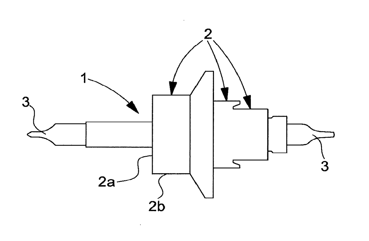
[0037]The invention relates to a component for a timepiece movement and particularly to a non-magnetic timepiece component, such as a pivot arbor, for a mechanical timepiece movement.
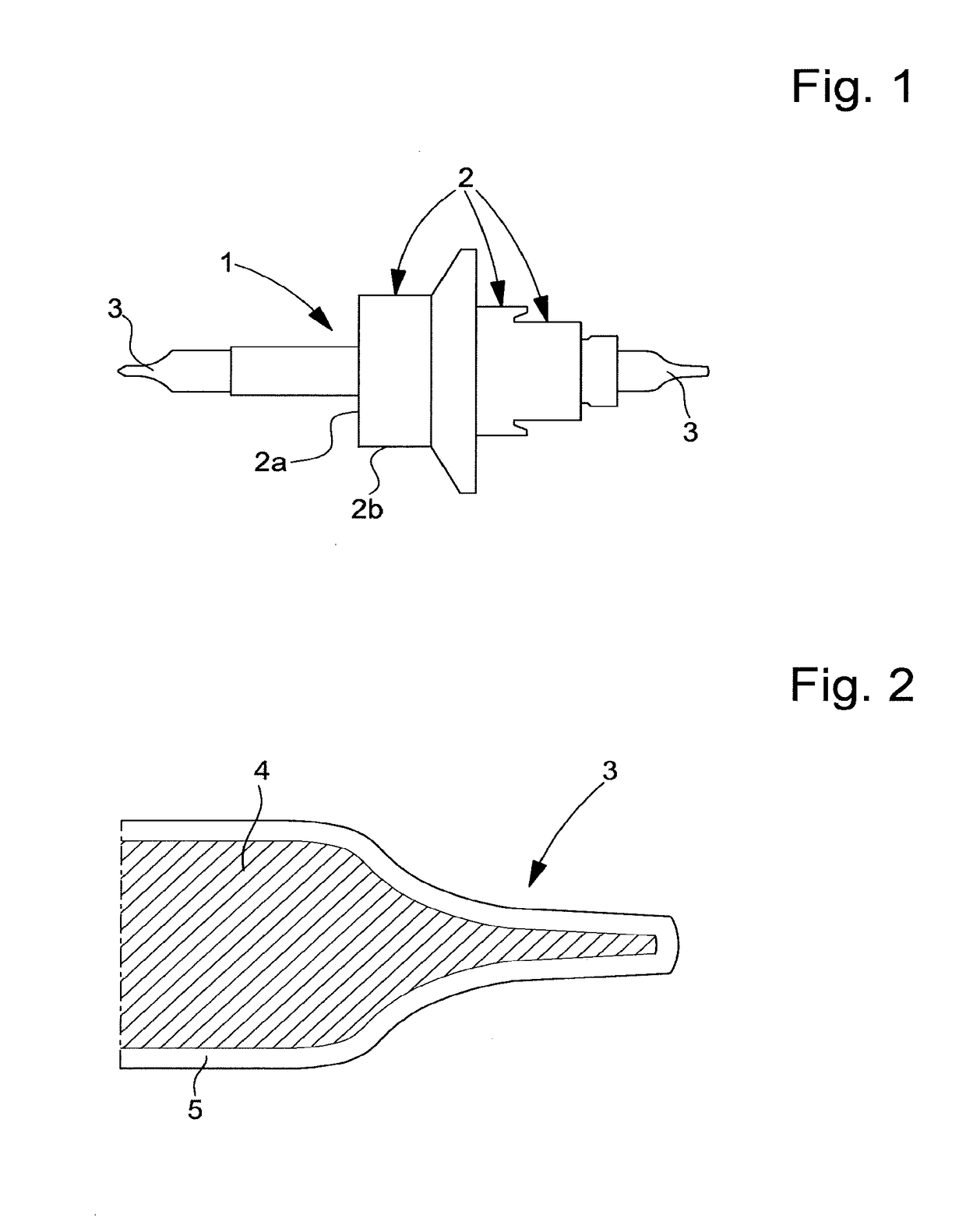
[0038]The invention will be described below with reference to an application to a non-magnetic balance staff 1. Of course, other types of timepiece pivot arbors may be envisaged such as, for example, timepiece wheel set arbors, typically escape pinions or pallet staffs. Components of this type have a body with a diameter preferabl...
PUM
 Abstract
Description
Claims
Application Information