Multicast path building method and device

a multicast path and path technology, applied in the field of multicast relay technique, can solve the problem of inability to guarantee the load splitting between a router and the lines constituting the ecmp, and achieve the effect of ensuring the load splitting between the router and the lin

Inactive Publication Date: 2009-05-28
ALAXALA NETWORKS
View PDF5 Cites 22 Cited by
  • Summary
  • Abstract
  • Description
  • Claims
  • Application Information

AI Technical Summary

Benefits of technology

[0017]The present invention selects an RPF Neighbor according to the estimated traffic flow rate and can guarantee the load splitting between adjacent routers and lines constituting an ECMP regardless of the traffic contents.

Problems solved by technology

For this, it is impossible to guarantee the load splitting between a router and lines constituting the ECMP.

Method used


Image

  • Multicast path building method and device
  • Multicast path building method and device
  • Multicast path building method and device

Examples


Embodiment Construction

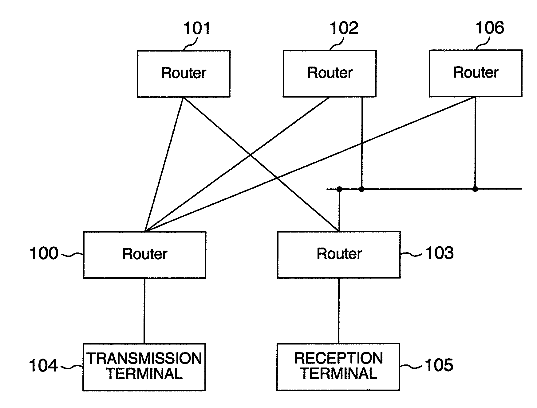
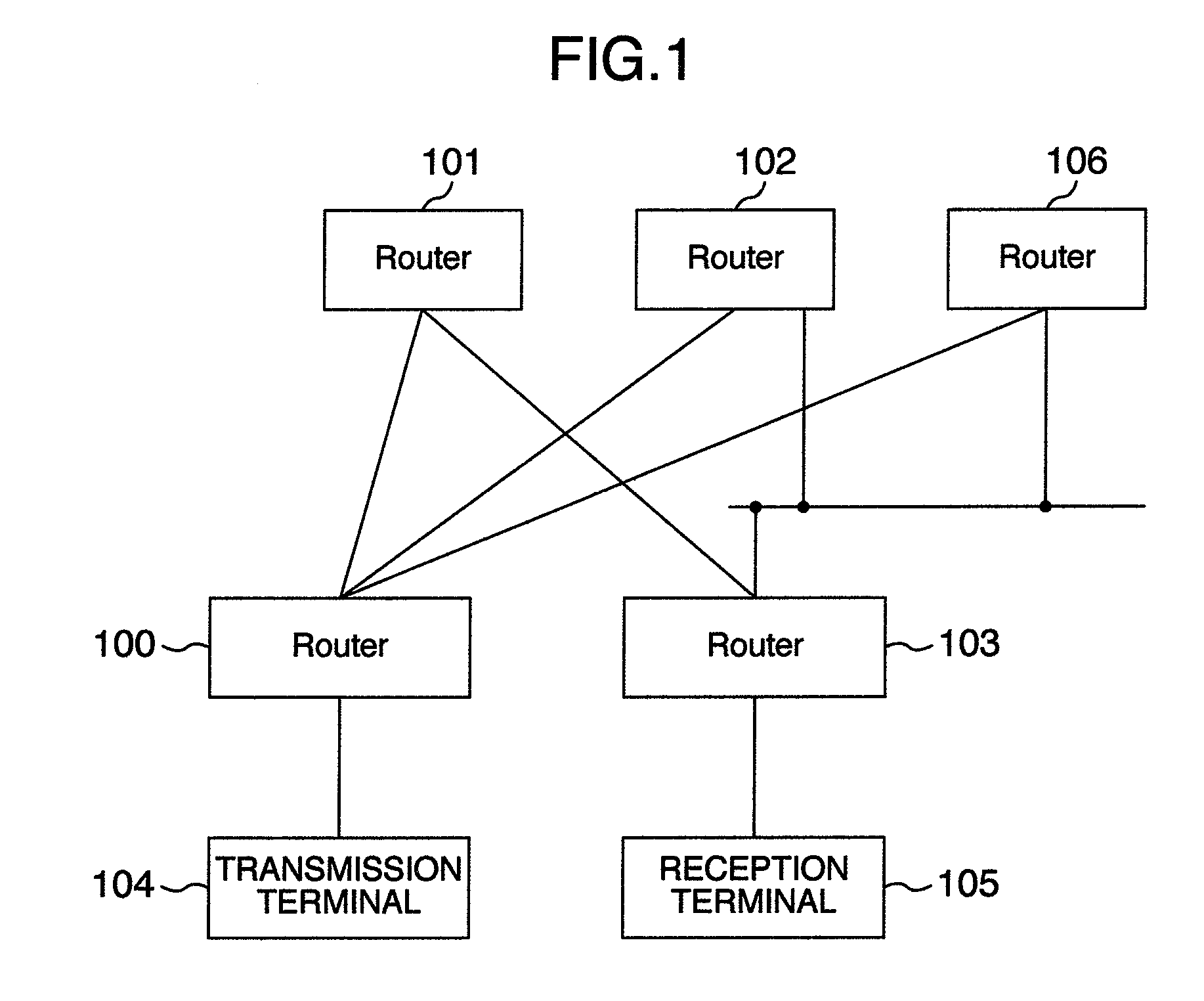
[0028]FIG. 1 shows an example of the PIM-SM multicast network according to an embodiment of the present invention. The PIM-SM multicast network includes PIM-SM routers 100-103, 106, a transmission terminal 104, and a reception terminal 105. When the reception terminal 105 transmits a request for participating in the multicast group (multicast reception request) from the transmission terminal 104, a router 103 containing the reception terminal 105 calculates the RPF Neighbor of the direction of the transmission terminal 104 and transmits a PIM join message to the router. In the case of FIG. 1, the ECMP configuration is realized since the distances from the router 103 to the transmission terminal 104 though the routers 101, 102, 106 are identical. Here, the router 103 selects one of the routers (for example, router 101) as the RPF Neighbor and transmits a PIM join message. Here, the router 103 registers the inverse path against the direction in which the PIM join message has been tran...


PUM


Abstract

An RPF Neighbor having the least traffic flow is estimated and a multicast distribution path via the RPF Neighbor is selected so as to split the load between routers constituting the Equal-cost Multipath and lines.

Description

INCORPORATION BY REFERENCE[0001]The present application claims priority from Japanese application JP2007-306744 filed on Nov. 28, 2007, the content of which is hereby incorporated by reference into this application.BACKGROUND OF THE INVENTION[0002]The present invention relates to the multicast relay technique in the Internet and in particular, to the multicast path building technique and the load splitting technique in the multicast network using the equal-cost multipath.[0003]The multicast is a technique used in the Internet by a router to copy and output a packet to a plurality of lines so that one transmitted packet is simultaneously transmitted to a plurality of receivers. Since it is possible to transmit a packet with a small quantity of packet to a plurality of transmission destinations as compared to the transmission of a packet to one transmission destination by a plurality of times, the multicast technique is appropriately used in a real time medium requiring a large-capaci...

Claims


Application Information

Patent Timeline
Patent Type & Authority Applications(United States)
IPC IPC(8): H04L12/56H04L45/16
CPCH04L45/02H04L45/60H04L45/16
Inventor SUZUKI, SHINSUKE
Owner ALAXALA NETWORKS
Why Eureka
Try Eureka