
Drumless Cable Reel

a reel and reel technology, applied in the field of reels for fiber optic cables and assemblies, can solve the problems of large loose coils that are difficult to manage in the field and/or factory, add considerable expense to the manufacturing of fiber optic cables and/or assemblies, and cost of providing a conventional reel with a solid drum

Inactive Publication Date: 2009-05-28
CORNING OPTICAL COMM LLC
View PDF5 Cites 13 Cited by
  • Summary
  • Abstract
  • Description
  • Claims
  • Application Information

AI Technical Summary

Benefits of technology

[0005]Disclosed are disposable reels and assemblies for holding a cable, thereby aiding the craft in routing cables such as fiber optic drop cables. The reel has a first flange having at least one first tab and at least one first tab slot and a second flange having at least one second tab and at least one second tab slot. Before assembly, the respective tabs on the first flange and second flange are disposed generally in same respective planes of the first flange and the second flange. To assemble the reel, the respective tabs of the flanges are pushed outward (i.e., folded out) from the respective planes of the first flange and second flange. Thereafter, the first flange is attached to the second flange to form the disposable reel by at least one first tab engaging at least on second tab slot and at least one second tab engaging the at least one first tab slot, thereby forming a hub for the disposable reel that has an accessible space therein. Additionally, fiber optic cable assemblies can further include a connector such as a hardened connector or a non-hardened connector on one or more ends.

Problems solved by technology

The large loose coils can be difficult to manage in the field and / or factory.
The cost of providing a conventional reel having a solid drum for each these loose coils adds considerable expense for manufacturing the fiber optic cable and / or assembly.
Moreover, the craft would have to either dispose or return the conventional reels, which would take up considerable space in vehicles.

Method used


Image

  • Drumless Cable Reel
  • Drumless Cable Reel
  • Drumless Cable Reel

Examples


Embodiment Construction

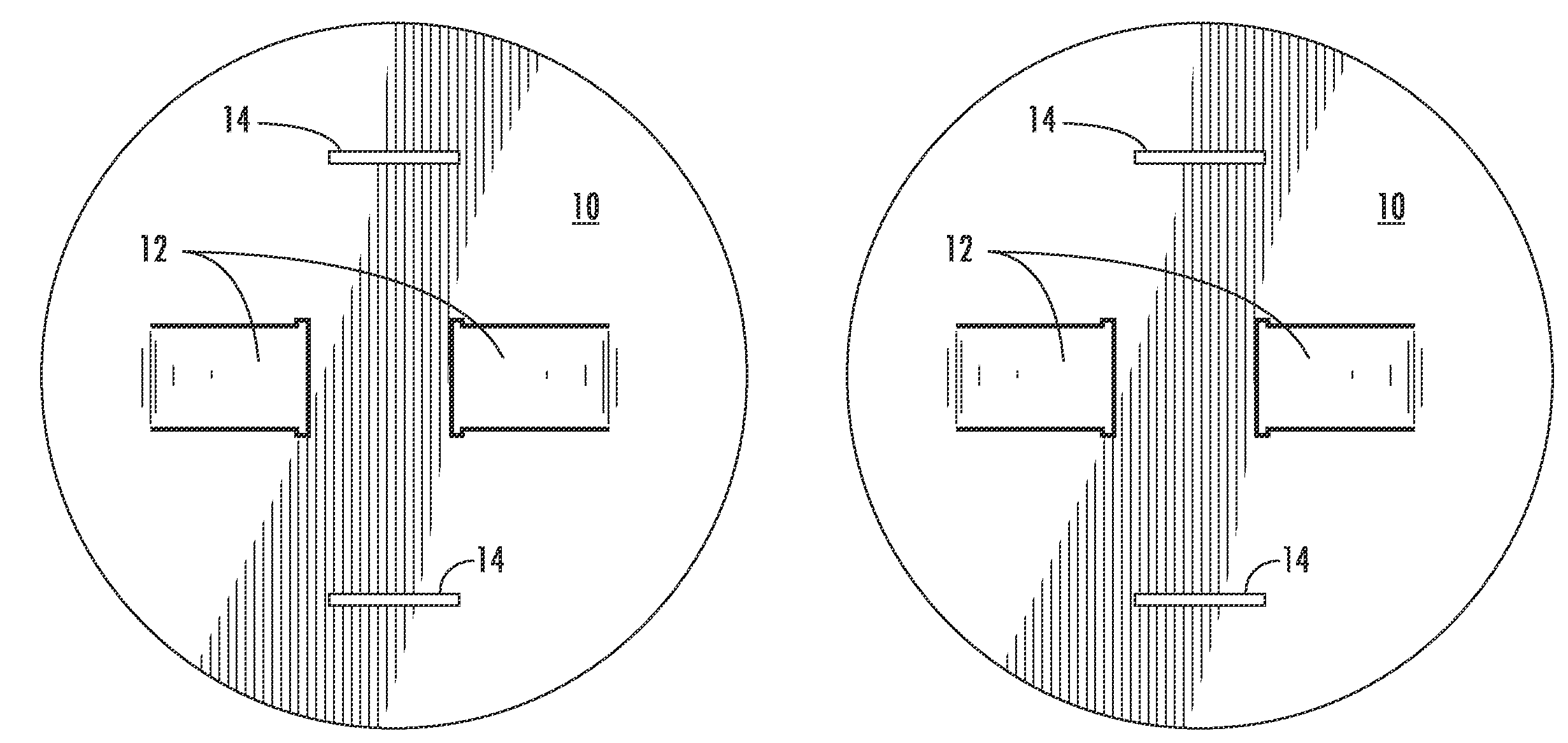
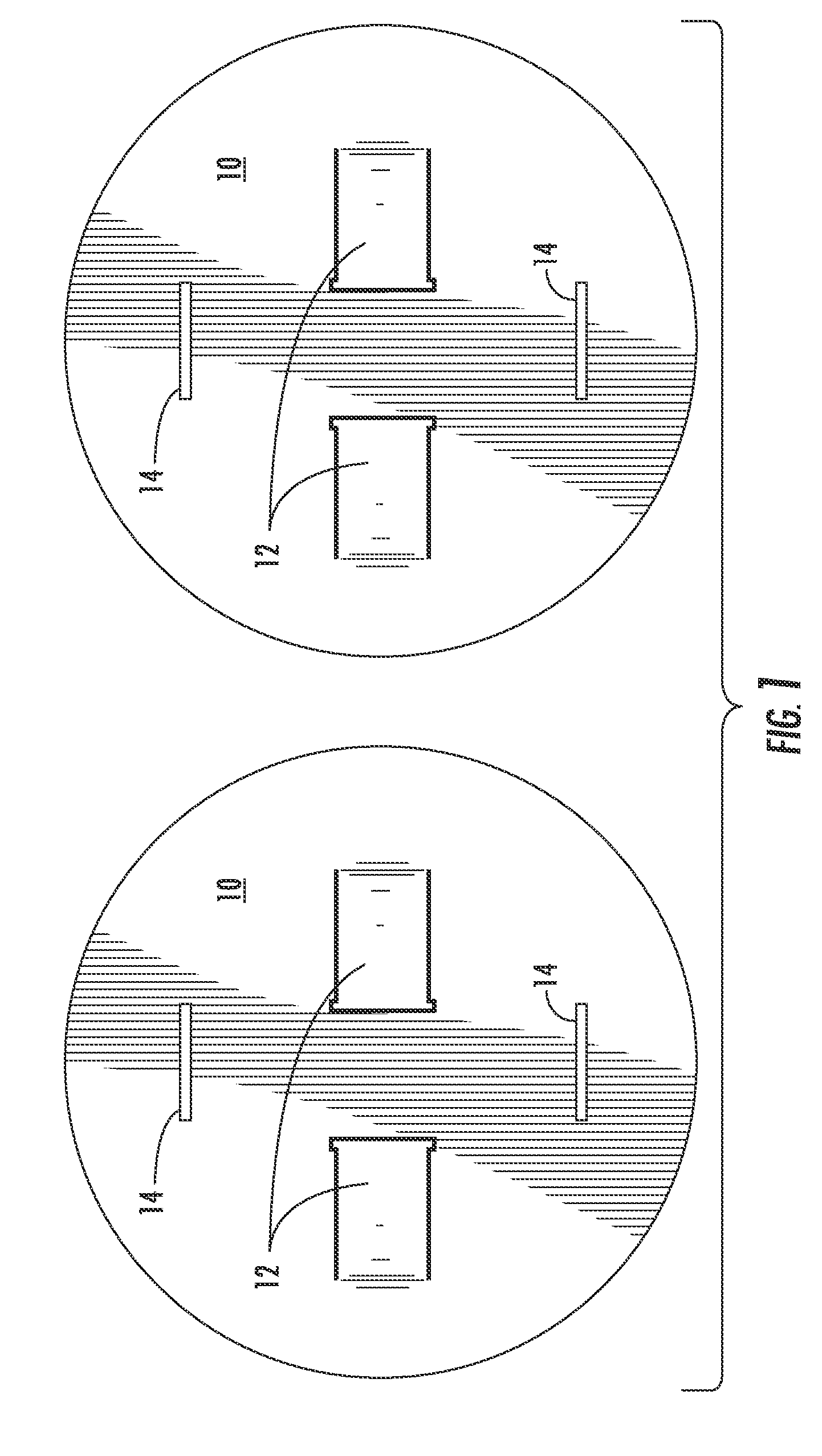
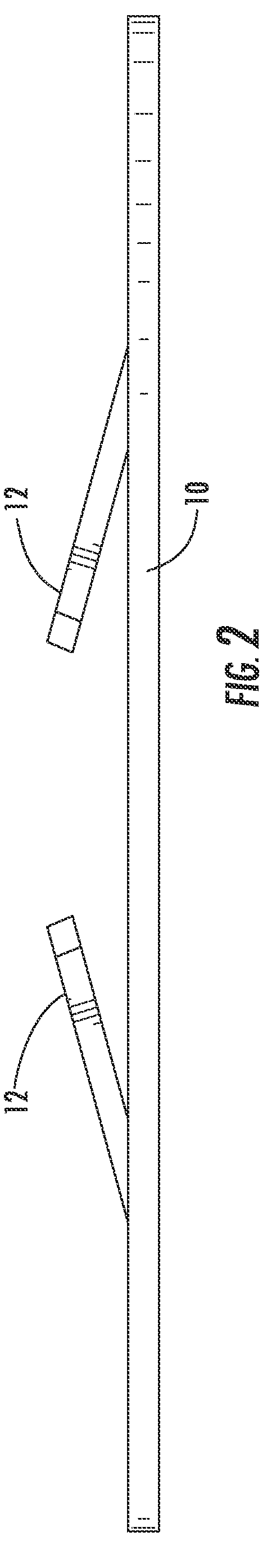
[0015]Reference will now be made in detail to the preferred embodiments, examples of which are illustrated in the accompanying drawings. Whenever possible, like reference numbers will be used to refer to like components or parts. FIG. 1 depicts a plan view for a set of exemplary flanges 10 for constructing a reel 100 (i.e., a first flange and a second flange assembled together) according to the present invention. As shown, flanges 10 are similar in shape and size such as round, but other shapes or sizes are possible. As shown, flanges 10 are identical (but could be similar or dissimilar) circular flanges stamped from corrugated plastic, cardboard, solid plastic, corrugated paper, or other suitable material for making reel 100. Each flange 10 has a plurality of tabs 12 such as two tabs punched into flange 10 and a plurality of tab slots 14 (i.e., knockouts) that are matched to the spacing on the tabs (e.g., about 180 degrees for two, about 120 degrees for three, etc.). By way of exam...


PUM


Abstract

Disclosed are disposable reels and assemblies for holding a cable, thereby aiding the craft in routing cables such as fiber optic drop cables. The reel has a first flange having at least one first tab and at least one first tab slot and a second flange having at least one second tab and at least one second tab slot. First flange is attached to the second flange to form the disposable reel by at least one first tab engaging at least on second tab slot and at least one second tab engaging the at least one first tab slot, thereby forming a hub for the disposable reel that has an accessible space therein. Additionally, fiber optic cable assemblies can further include a connector on one or more ends.

Description

RELATED APPLICATIONS[0001]The present application claims priority to U.S. Provisional Patent Application Ser. No. 61 / 004,453 titled “Drumless Cable Reel,” which is incorporated herein by reference in its entirety.FIELD OF THE INVENTION[0002]The present invention relates to reels for fiber optic cables and assemblies. More specifically, the present invention relates to a small form factor reel that is easy to assemble and use for providing the craft with a packaged solution for fiber optic cable and / or assemblies.TECHNICAL BACKGROUND[0003]Fiber optic cables are being routed deeper into communication networks for increasing the bandwidth available to the subscriber. For instance, fiber optic cables are being routed to the premises of subscribers for fiber to the home (FTTH) applications. Currently, fiber optic drop cables are wound on relatively large drums during manufacturing and the like, then removed therefrom as a relatively large coil such as a 16″ coil, which is a limitation of...

Claims


Application Information

Patent Timeline
Patent Type & Authority Applications(United States)
IPC IPC(8): G02B6/00
CPCB65H75/22B65H75/285H02G11/02B65H2701/534G02B6/4457B65H2701/32B65H75/2227B65H75/229
Inventor JENSEN, JOSEPH C.
Owner CORNING OPTICAL COMM LLC
Learn More