Eureka AIR delivers breakthrough ideas for toughest innovation challenges, trusted by R&D personnel around the world.

Threaded screw fastener

Inactive Publication Date: 2009-05-28
ILLINOIS TOOL WORKS INC
View PDF23 Cites 13 Cited by
  • Summary
  • Abstract
  • Description
  • Claims
  • Application Information

AI Technical Summary

Benefits of technology

[0019]In this manner, the threaded screw fastener of the present invention reduces the number of rotations required to drive the fastener into the materials to be fastened (since a portion of the fastener, that being the ballistic point and the linear travel area, is linearly, and not rotatably, driven into the materials).
[0020]Moreover, the configuration of the ballistic point creates an opening in the substrate material during the linear driving process that facilitates engagement of the threaded area of the shank. When the substrate material comprises steel, such as a steel stud, the opening created by the ballistic point includes a collar-like structure that provides additional material with which the threaded portion of the fastener may engage, thereby increasing pull-out resistance.

Problems solved by technology

However, known prior art devices rotate the faster as it is driven into the material since prior art threaded screw fasteners are formed with threads along essentially the entire length of the shank.
Moreover, when driving such fasteners into a relatively hard substrate material, such as steel or wood framing elements, additional force is required to cause the fastener to penetrate the substrate material and to engage the threads of the fastener with the substrate material.

Method used


Image

  • Threaded screw fastener
  • Threaded screw fastener
  • Threaded screw fastener

Examples


Embodiment Construction

[0030]While the present invention is susceptible of embodiment in various forms, there is shown in the drawings and will hereinafter be described a presently preferred embodiment with the understanding that the present disclosure is to be considered an exemplification of the invention and is not intended to limit the invention to the specific embodiment illustrated.

[0031]It should be further understood that the title of this section of this specification, namely, “Detailed Description Of The Invention,” relates to a requirement of the United States Patent Office, and does not imply, nor should be inferred to limit the subject matter disclosed herein.

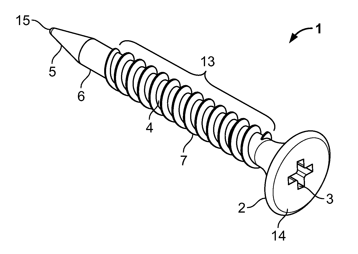
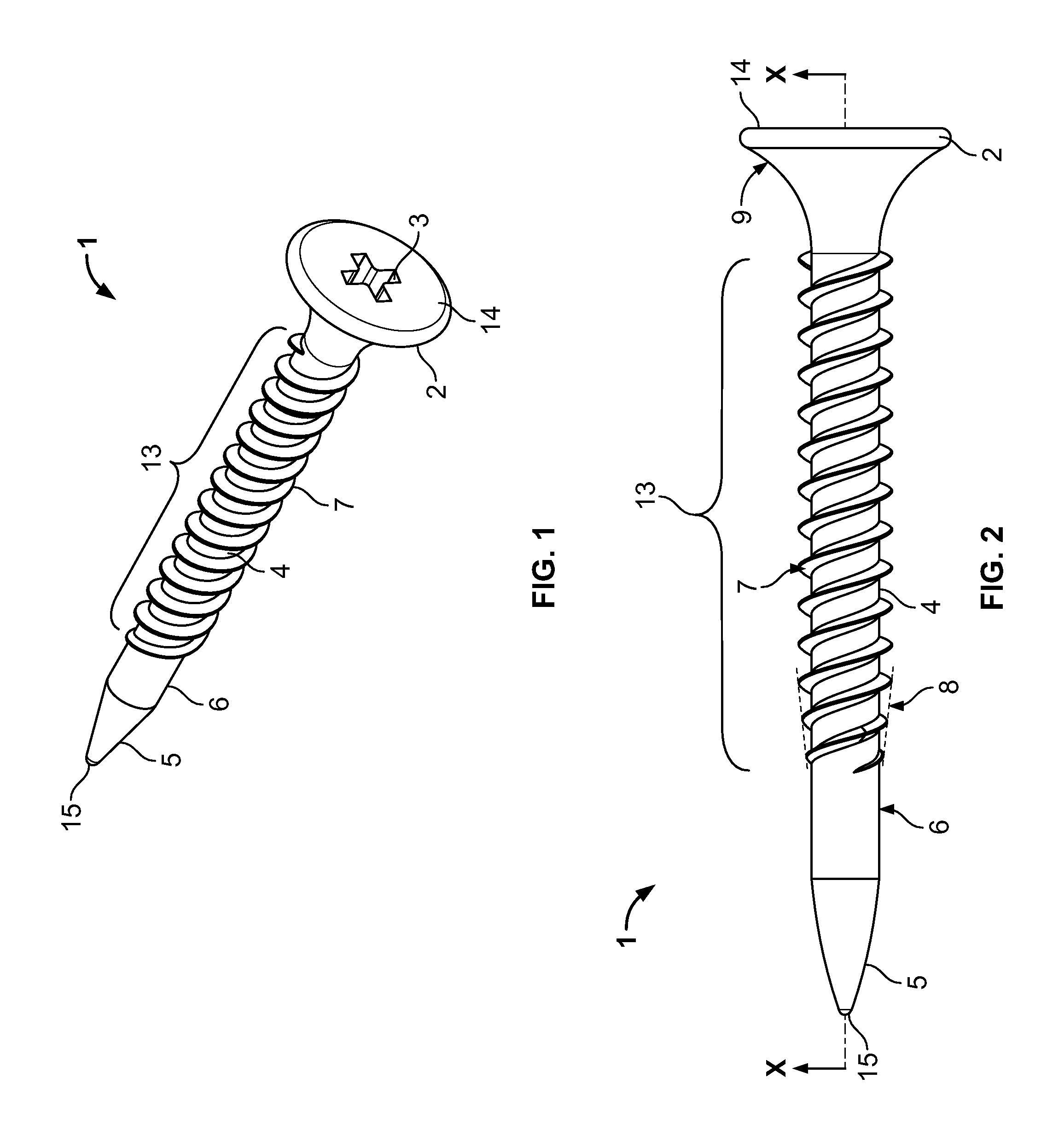
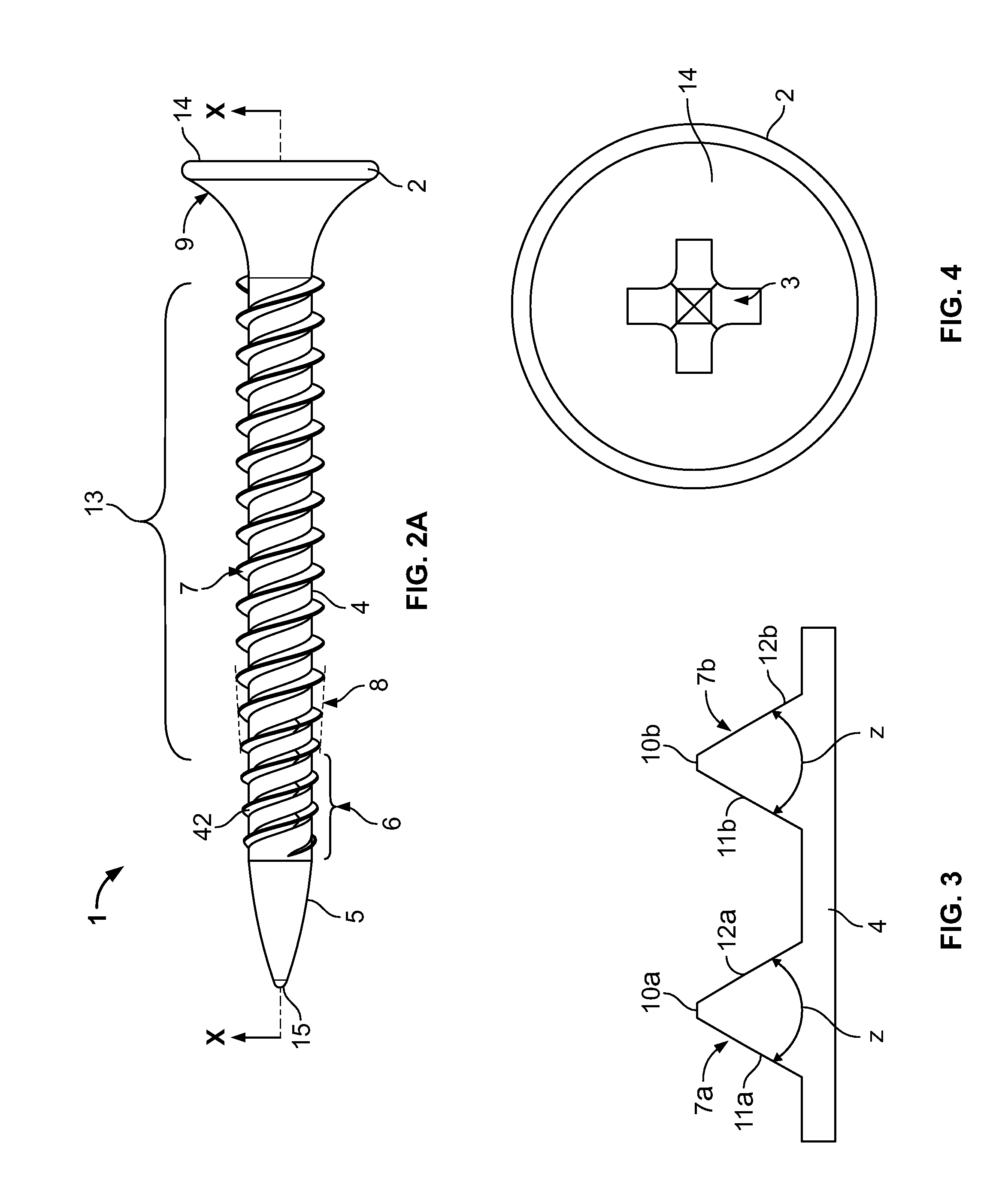
[0032]Referring to the figures and in particular to FIGS. 1 and 2, there is shown a threaded screw fastener 1 embodying the principles of the present invention.

[0033]Fastener 1 comprises a point 5, a shank 4 and a head 2. Point 5 is formed in a generally ballistic shape, having a rounded tip 15 at the distal end of fastener 1 (distal mos...


PUM

PropertyMeasurementUnit
Angleaaaaaaaaaa
Angleaaaaaaaaaa
Shapeaaaaaaaaaa

Abstract

A threaded screw fastener has a point, a shank and a head. The point is a ballistic point. The shank comprises a linear travel area, preferably unthreaded, adjacent to the point and a threaded area between the linear travel area and the head. The head is a bugle head formed with a Phillips-style recess configured to receive a driver or driving bit. The fastener is configured fasten a surface material to a substrate material and to be linearly driven into the materials before rotation of the fastener is required, thus reducing the number of rotations required to drive the fastener. The fastener is particularly suited to be used with powered driving tools that utilize both linear and rotating driving means.

Description

BACKGROUND OF THE INVENTION[0001]The present invention relates generally to threaded screw fasteners, and more particularly to an improved threaded screw fastener configured with a ballistic point adjacent to a linear travel area on the shank to allow the fastener to be driven into a material before the fastener is rotated.[0002]Threaded screw fasteners are well known in the art and are widely used for numerous fastening applications. In one such application, threaded screw fasteners are used to fasten a surface material, such as exterior gypsum sheathing or interior dry wall, to a substrate material, such as steel or wood framing elements (for example, wood or light gauge steel studs).[0003]For use in such applications, the threaded screw fastener typically is formed with a bugle head (oftentimes having a recess configured to receive a Phillips-head driver or driving bit), a threaded shank (with either single lead or double lead threads) and a sharp point or tip. In some embodiment...

Claims


Application Information

Patent Timeline
IPC IPC(8): F16B23/00B23P19/06
CPCF16B25/0031Y10T29/5343F16B25/103F16B25/0047
Inventor PANASIK, CHERYL L.MANSOUR, NAIMGONG, YONGPING
Owner ILLINOIS TOOL WORKS INC
Why Eureka
Eureka Blog
Learn More