Prism unit and a projection image display apparatus

a projection image and display apparatus technology, applied in the field of prism units, can solve the problems of deterioration of optical performance and optical performance, and achieve the effects of reducing the use environment of the prism base, reducing the risk of deterioration, and high environmental reliability

Active Publication Date: 2009-06-04
CANON KK
View PDF6 Cites 29 Cited by
  • Summary
  • Abstract
  • Description
  • Claims
  • Application Information

AI Technical Summary

Benefits of technology

[0009]The present invention is also directed to a prism unit which controls a position of a seating surface to a prism optical surface, and prevents the deterioration of the optical performance even if the environmental conditions change.
[0013]The prism unit according to the present invention can precisely maintain a positional relationship among the prisms, high environmental reliability, and highly reliable adhesion by using a plurality of seating surfaces provided on the prism base in bonding the prisms to the prism base.
[0014]A revolution of the optical surface that would otherwise caused by the stress generated due to the difference in coefficient of linear expansion among the prisms and the prism base in its use environment can be minimized by controlling a position of the seating surface of the prism base to the prism's optical surface

Problems solved by technology

If an ambient temperature changes due to the bonding condition of the prisms to the prism base, the orientation of the prism may change or the prism may break; when the orientation of the prism changes and the relative positional relationship changes, the optical performance may deteriorate.
The deterioration of the optical performance may also occur when the prism falls in the seating surface direction because the optical axis falls concurrently.

Method used


Image

  • Prism unit and a projection image display apparatus
  • Prism unit and a projection image display apparatus
  • Prism unit and a projection image display apparatus

Examples


embodiment 1

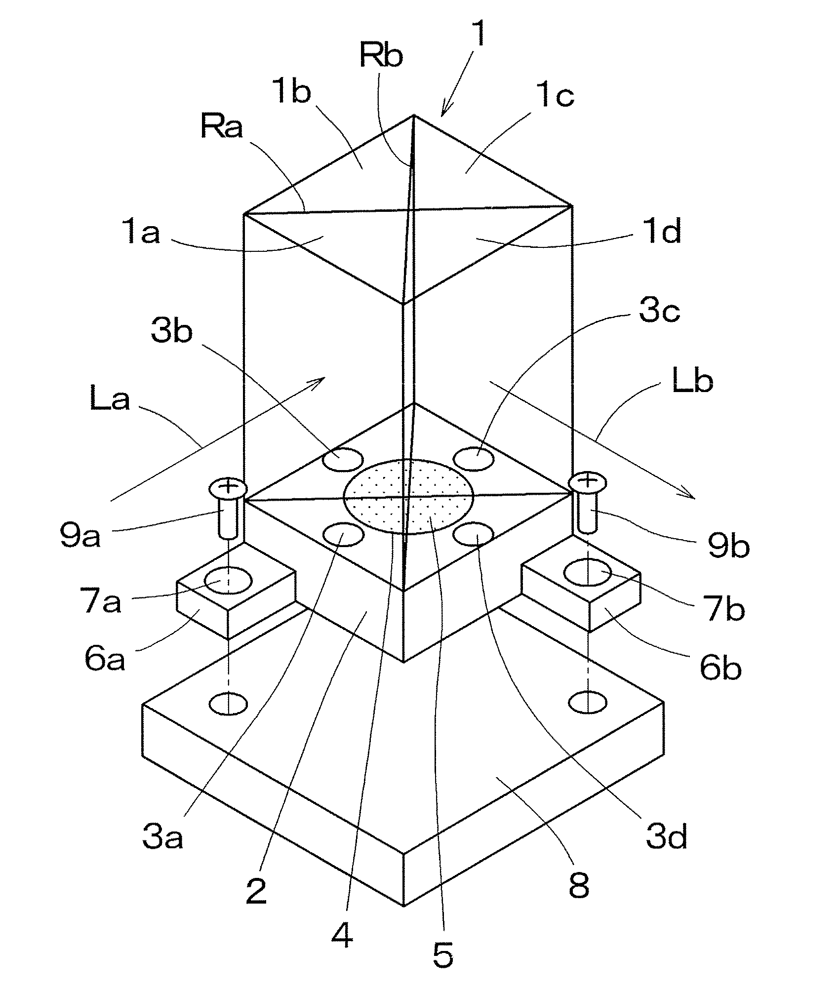
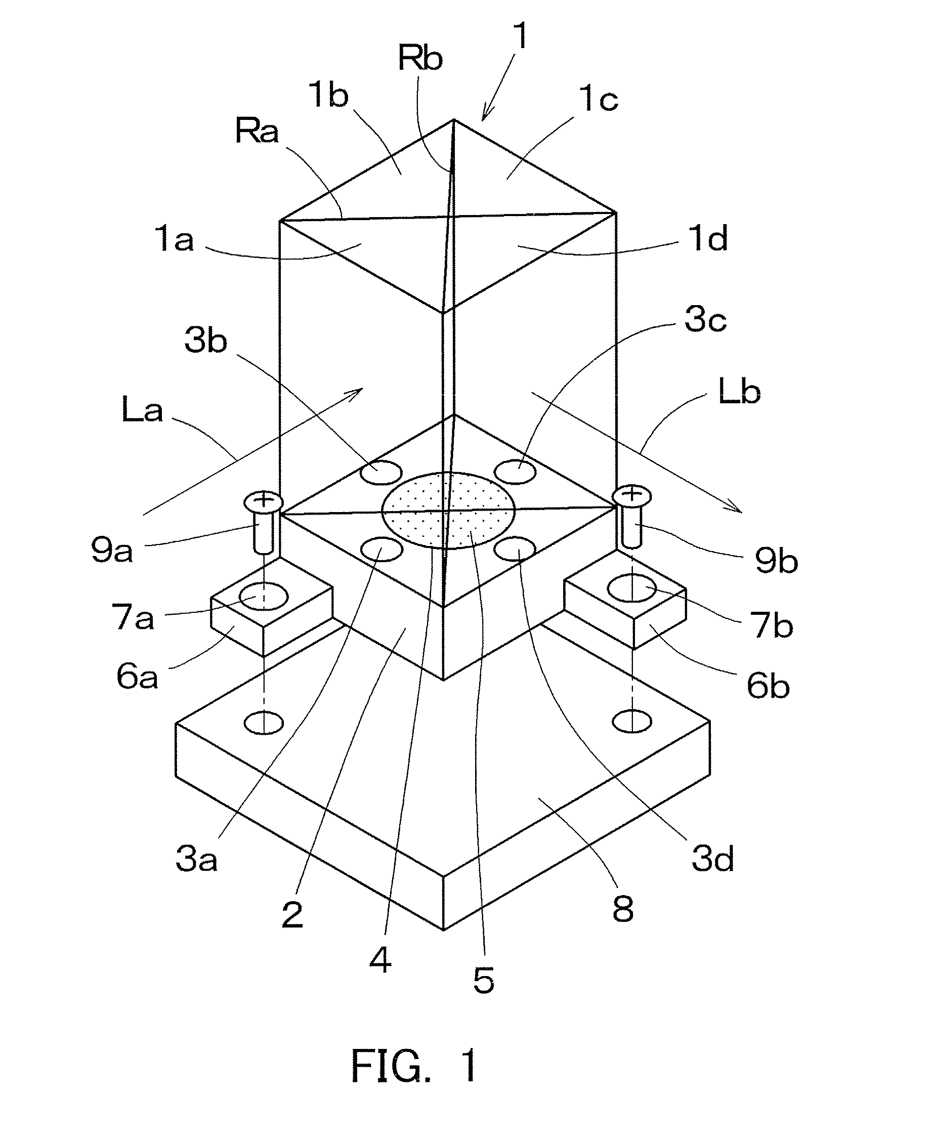
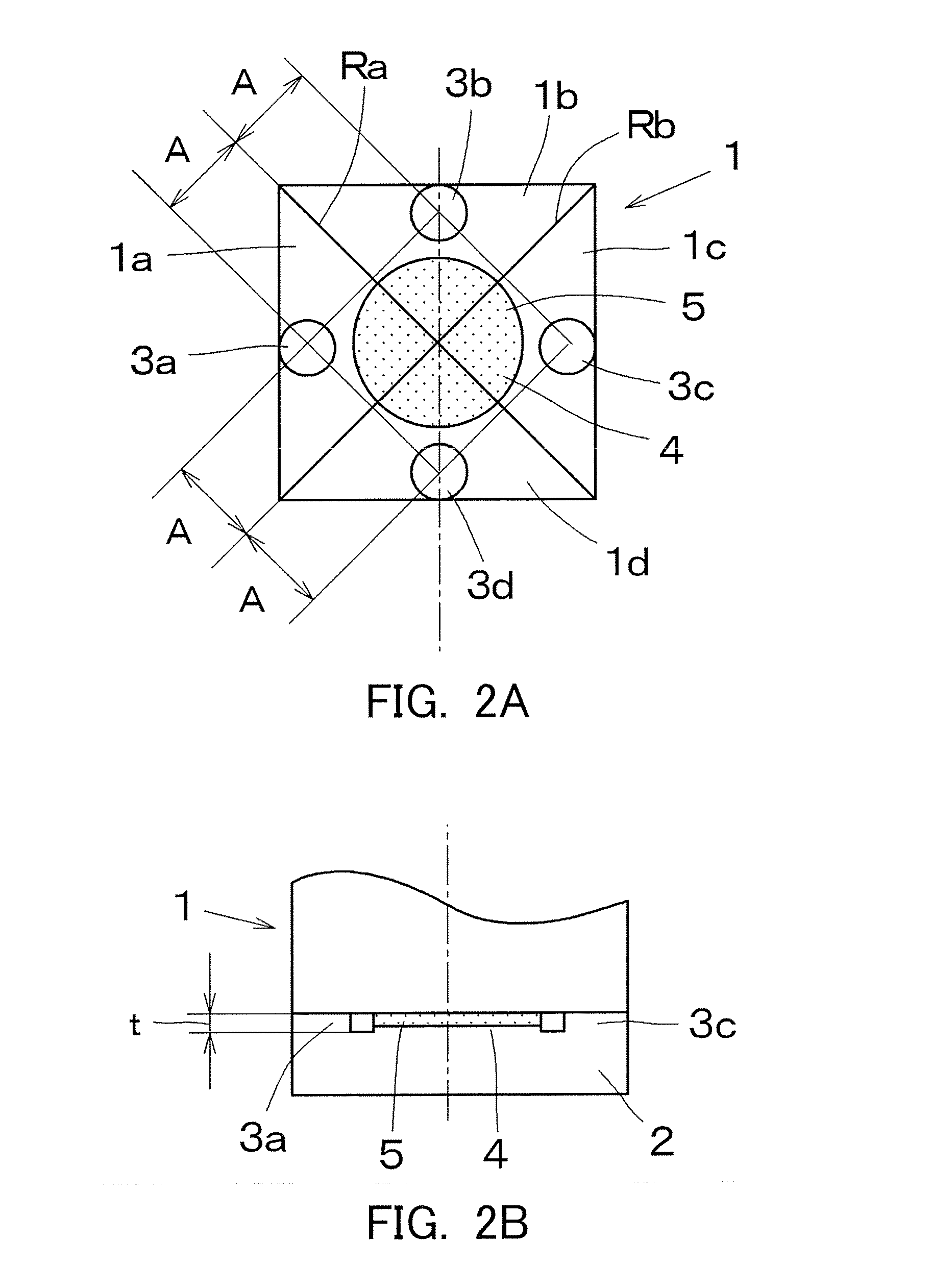
[0048]FIG. 1 is a perspective view of a prism unit which is formed by bonding a prism 1 to a prism base 2. Four rectangular-equilateral-triangle columnar prism members 1a are bonded to the prism 1, and the prism 1 has a square shape. At least three (or four in this embodiment) circular seating surfaces 3a to 3d that maintain parallelisms are disposed on the prism base 2. Two seating surfaces 3 are arranged on both sides of each of a reflecting surface (an optical surface) Ra that serves as a joining surface between prism members 1a and 1b and between prism members 1c and 1d and a reflecting surface (an optical surface) Rb that serves as a joining surface between 1a and 1d and between prism members 1b and 1c.

[0049]The prism 1 is positioned by bringing it into contact with the seating surfaces 3a to 3d, and has a seating surface bonded part 4 surrounded by the seating surfaces 3a to 3d, and formed on a surface of the prism base 2 located at a distant position; the prism 1 is bonded t...

embodiment 2

[0068]FIG. 8 is a perspective view of a prism unit according to a second embodiment. FIG. 9 is a plan view, FIG. 10 is a side view, and FIG. 11 is a sectional view of the prism unit. Three prisms 11, 12, and 13 are pasted onto one connection prism base 14. Three circular seating surfaces 15a to 15c are respectively disposed on the top surface of the connection prism base 14 to which the prisms 11 to 13 are joined, and the seating surfaces 15a to 15c are formed with defined parallelisms. Accordingly, the precision in the positional relationship between each other is ensured by placing the bottom surfaces of the prisms 11 to 13 on three seating surface 15a to 15c. Further, the seating surface bonded part 16 is disposed on the connection prism base 14 in a slightly lower position than the three seating surfaces 15a to 15c.

[0069]Although the above description has been given of the circular seating surfaces 15a to 15c and the circular seating surface bonded part 16, FIG. 12 shows a vari...

embodiment 3

[0070]FIG. 13 is a perspective view of a prism unit according to a third embodiment, which has a groove 21 configured to store extra adhesive 5 on the prism base 2 in addition to the structure of the prism unit in FIG. 1. Those reference numerals in FIG. 13, which are designated by the same reference numerals in FIG. 1, will be the same elements in FIG. 1.

[0071]In the arrangement of the seating surfaces 3 and the seating surface bonded part 4 according to the first embodiment, the adhesive 5 may stick out of the seating surface bonded part 4 in applying the adhesive 5 to the seating surface bonded part 4 that is slightly lower than the prism base 2 for the UV adhesion. Conceivably, the adhesive 5 which sticks out enters a small aperture between the seating surfaces 3a to 3d and the prism 1, and will bond them together.

[0072]In FIG. 13, the circular seating surface bonded parts 4 neighbor at four spots between the seating surfaces 3a to 3d and the seating surface bonded parts 4 on th...


PUM


Abstract

A prism unit includes a prism having at least one optical surface in its inside, and a prism base disposing the prism, the prism base including at least three seating surfaces that are attached to a surface orthogonal to the optical surface of the prism, a seating surface bonded part that is bonded to the prism by an adhesive. At least the three seating surfaces and the seating surface bonded part are symmetrically arranged on the optical surface of the prism.

Description

BACKGROUND OF THE INVENTION[0001]1. Field of the Invention[0002]The present invention relates to a prism unit that is used for a reflection-type projector apparatus or the like.[0003]2. Description of the Related Art[0004]Conventional reflective liquid crystal projectors which implement color separation and color composition with an optical system using a plurality of reflective liquid crystal panels for chromatic light generally comprise optical systems of the color separation or the color composition by using a polarized light beam splitter prism or dichroic prism. These optical systems use a plurality of prisms, and a relative positional relationship among the light incident prism surfaces directly influences the image quality, such as contrast deteriorations due to the prism's falls and positional shifts of pixels of each chromatic light, or a shift of the illumination optical axis to the liquid crystal panel.[0005]Accordingly, a prism base used to constitute an integral prism u...

Claims


Application Information

Patent Timeline
Patent Type & Authority Applications(United States)
IPC IPC(8): G02B27/10G02B5/04
CPCG02B5/04G02B7/181G02B7/1805
Inventor KOYAMA, TAKEHIRO
Owner CANON KK
Why Eureka
Try Eureka