Optical unit and method for manufacturing the same

A technology for optical units and manufacturing methods, applied to optical components, optics, instruments, etc., which can solve problems such as rising costs of fixed units

Pending Publication Date: 2019-09-03
KONICA MINOLTA INC
View PDF11 Cites 0 Cited by
  • Summary
  • Abstract
  • Description
  • Claims
  • Application Information

AI Technical Summary

Problems solved by technology

[0005] However, in the case of this optical unit, lenses other than the front lens need to be piled up and fix

Method used


Image

  • Optical unit and method for manufacturing the same
  • Optical unit and method for manufacturing the same
  • Optical unit and method for manufacturing the same

Examples


no. 1 approach 〕

[0024] Hereinafter, an optical unit and an imaging device including the optical unit according to a first embodiment of the present invention will be described with reference to the drawings.

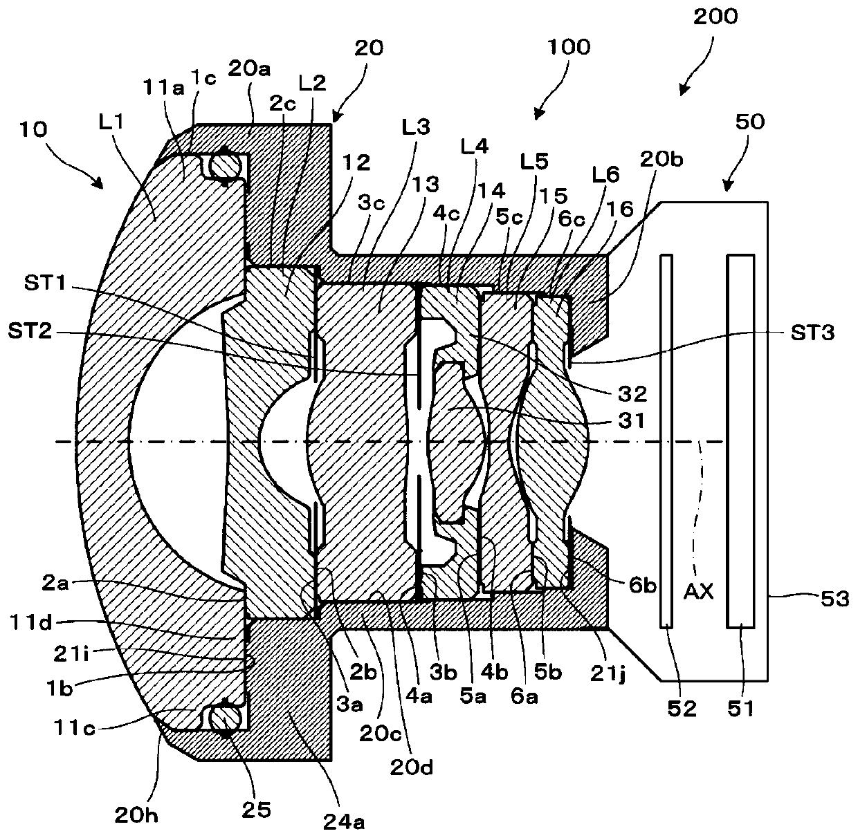
[0025] Such as Figure 1A As shown, the optical unit 100 is combined with the sensor unit 50 to constitute the imaging device 200 . The optical unit 100 includes an imaging optical system 10 and a lens holder 20 that accommodates the imaging optical system 10 . The photographing optical system 10 is composed of first to sixth lenses L1 to L6. Among the first to sixth lenses L1 to L6, the first to third lenses L1 to L3 and the fifth and sixth lenses L5 and L6 are optical lenses made of resin, and the fourth lens L4 has a lens body 31 made of glass, and This lens main body 31 is attached to the optical lens of the resin-made lens frame 32 inside. A stop ST1 is interposed between the second lens L2 and the third lens L3, a stop ST2 is interposed between the lens frame 32 of the third len...

no. 2 approach 〕

[0038] Hereinafter, the optical unit according to the second embodiment will be described. In addition, the optical unit of the second embodiment is obtained by modifying the optical unit of the first embodiment, and matters not particularly described are the same as those of the first embodiment and the like.

[0039] Such as Figure 4A As shown, the optical unit 100 includes an imaging optical system 10 and a lens holder 20 that accommodates the imaging optical system 10 . The imaging optical system 10 is composed of first to sixth lenses L1 to L6, and includes stops ST1 to ST3 as other optical components.

[0040] In this case, the stop ST2 is a resin sheet member functioning as the second member, and has a thickness of about several 10 μm. The stop ST2 is not limited to a stop for adjusting the opening, and may be used for light beam limitation or for ghost countermeasures. The stop ST2 has an abutment surface 8 a perpendicular to the optical axis AX on the third lens L...

no. 3 approach 〕

[0044] Hereinafter, an optical unit according to a third embodiment will be described. In addition, the optical unit of the third embodiment is obtained by modifying the optical unit of the first embodiment, and matters not particularly described are the same as those of the first embodiment and the like.

[0045] Such as Figure 5A As shown, the optical unit 100 includes an imaging optical system 10 and a lens holder 20 that accommodates the imaging optical system 10 . The imaging optical system 10 is composed of first to sixth lenses L1 to L6, and includes stops ST1 to ST3 as other optical components.

[0046] In this case, only the first lens L1 is independently fixed to the lens holder 20 , and the second to sixth lenses L2 to L6 are supported on the lens holder 20 in a stacked state. In other words, the second to sixth lenses L2 to L6 are held in the lens holder 20 in a fitted state, positioned in a direction perpendicular to the optical axis AX, and movable or slidable...


PUM

PropertyMeasurementUnit
Wall thicknessaaaaaaaaaa

Abstract

The invention provides an optical unit and a method for manufacturing the same, which can realize simplification of structure, easiness in assembly, low cost and prevention of optical performance degradation. The optical unit includes a plurality of optical members including a plurality of lenses, and a lens holder (20) that supports the plurality of optical members in an overlapping state. Amongthe plurality of optical members, a first member disposed at an end in one direction along the optical axis AX direction is provided with an abutting surface which is an abutting surface that abuts against a predetermined surface of the lens holder. The lens holder includes a pressing portion that presses the plurality of optical members in another direction via the first member. The second memberamong the plurality of optical members or the support end of the lens holder in the other direction overlaps the plurality of optical members within the lens holder. When a predetermined pressing force in the other direction is applied to the first member by the pressing portion, the first member is deformed in the optical axis AX direction so as to allow the abutting surface of the first memberand the predetermined surface of the lens holder to be positioned and abutted against each other.

Description

technical field [0001] The present invention relates to an optical unit in which a plurality of optical components are stacked and assembled in a lens holder, and a method for manufacturing the optical unit. Background technique [0002] As a conventional optical unit, there is known an optical unit in which a plurality of lenses are stacked in a lens holder constituting the optical unit, and a sealing member (O-ring) is attached to the front lens and the next first lens for the purpose of waterproofing. In a state where the two lenses are in contact, the front end portion of the lens holder is thermally deformed to fix the front lens and other lenses (see Patent Document 1). [0003] However, in the case of the above-mentioned optical unit, it cannot be ensured that the front lens embedded in the sealing member must be assembled straight along the optical axis direction. If the lens holder is thermally deformed while pressing the front lens while the lenses are in contact,...

Claims


Application Information

Patent Timeline
IPC IPC(8): G02B7/02
CPCG02B7/021G02B7/02
Inventor 新谷昌之船桥章
Owner KONICA MINOLTA INC
Why Eureka
Try Eureka