Lens barrel and imaging device

A lens barrel and lens group technology, applied in image communication, camera focusing device, printing device, etc., can solve problems such as difficulty in maintaining the inherent optical performance of imaging lenses, changing positional relationships, and complicating mechanisms, and preventing optical performance. worsening effect

Active Publication Date: 2021-10-08
RICOH KK
View PDF7 Cites 0 Cited by
  • Summary
  • Abstract
  • Description
  • Claims
  • Application Information

AI Technical Summary

Problems solved by technology

[0003] Inserting another lens into the imaging lens may complicate the mechanism around the lens and change the positional relationship between the lens groups of the imaging lens
This makes it difficult to maintain the inherent optical performance of the imaging lens
As for adding macro converter lenses or extension tubes, these elements need to be attached or removed manually, which can be cumbersome for the user

Method used


Image

  • Lens barrel and imaging device
  • Lens barrel and imaging device
  • Lens barrel and imaging device

Examples


Embodiment Construction

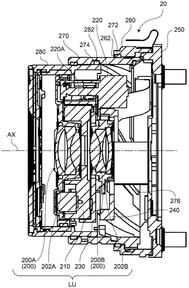
[0024] Hereinafter, a lens barrel according to an embodiment and an imaging apparatus including such a lens barrel will be described with reference to the drawings.

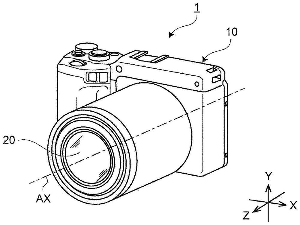
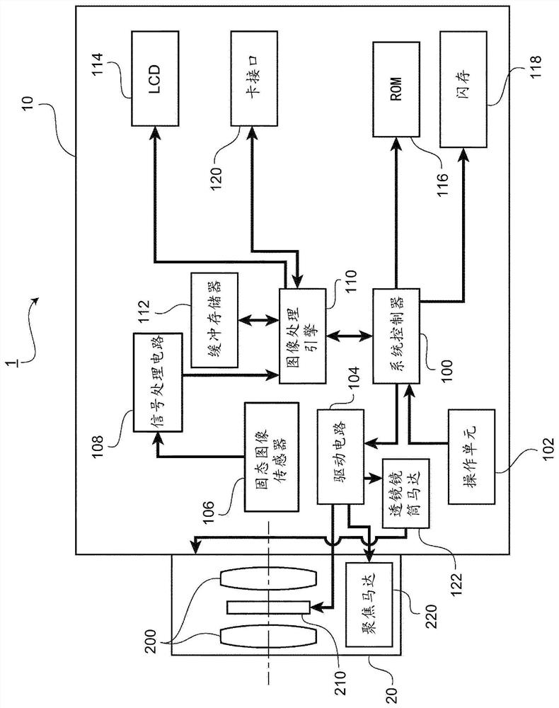
[0025] figure 1 is a schematic perspective view showing an imaging apparatus 1 according to an embodiment. figure 2 is a block diagram showing the structure of the imaging device 1 . Imaging devices include photographic functions such as single-lens reflex cameras, compact digital cameras, mirrorless single-lens cameras, video cameras, or camcorders.

[0026] like figure 1 and 2 As shown, the imaging device 1 includes a device body 10 and a lens barrel 20 . The apparatus main body 10 operates as a driving unit that applies driving force to the lens barrel 20 and controls the operation of the lens barrel 20 .

[0027] The device main body 10 includes a system controller 100, an operation unit 102, a drive circuit 104, a solid-state image sensor 106, a signal processing circuit 108, an image processing engine...


PUM


Abstract

A lens barrel includes a plurality of lens groups; a driver configured to move at least part of the plurality of lens groups along an optical axis for focusing; a holder configured to hold the plurality of lens groups and the driver; and a mover configured to move the plurality of lens groups and the driver together along the optical axis by moving the holder along the optical axis. The mover moves the holder to at least a first position at which a shooting distance of the lens barrel is changeable within a first range, and a second position at which the shooting distance of the lens barrel is changeable within a second range. The second range is shorter in minimum shooting distance than the first range.

Description

technical field [0001] The present invention relates to a lens barrel and an imaging device. Background technique [0002] Conventionally, in order to further shorten the minimum shooting distance of an imaging device, for example, an additional lens is inserted into the imaging lens, a macro conversion lens is attached to the imaging lens, or an extension tube is attached to a mount. [0003] Inserting another lens into the imaging lens may complicate the mechanism around the lens and change the positional relationship between the lens groups of the imaging lens. This makes it difficult to maintain the inherent optical performance of the imaging lens. As for adding a macro converter lens or extension tube, these elements need to be attached or removed manually, which can be cumbersome for the user. [0004] For example, Patent Document 1 describes a lens barrel with a foldable cam dedicated to a macro shooting mode that protrudes all lens groups to shorten the minimum sho...

Claims


Application Information

Patent Timeline
Patent Type & Authority Applications(China)
IPC IPC(8): G02B7/04G02B15/14G02B15/22
CPCG02B15/22G02B7/08G03B3/10G02B7/10H04N23/55
Inventor 铃木洋辅
Owner RICOH KK
Why Eureka
Try Eureka