
Earpiece Device with Microphone

a technology of earpiece and microphone, which is applied in the manufacture/assembly of earpiece/earphones, loudspeakers, instruments, etc., to achieve the effect of effectively avoiding the influence of background nois

Active Publication Date: 2009-06-04
MERRY ELECTRONICS CO LTD
View PDF9 Cites 10 Cited by
  • Summary
  • Abstract
  • Description
  • Claims
  • Application Information

AI Technical Summary

Benefits of technology

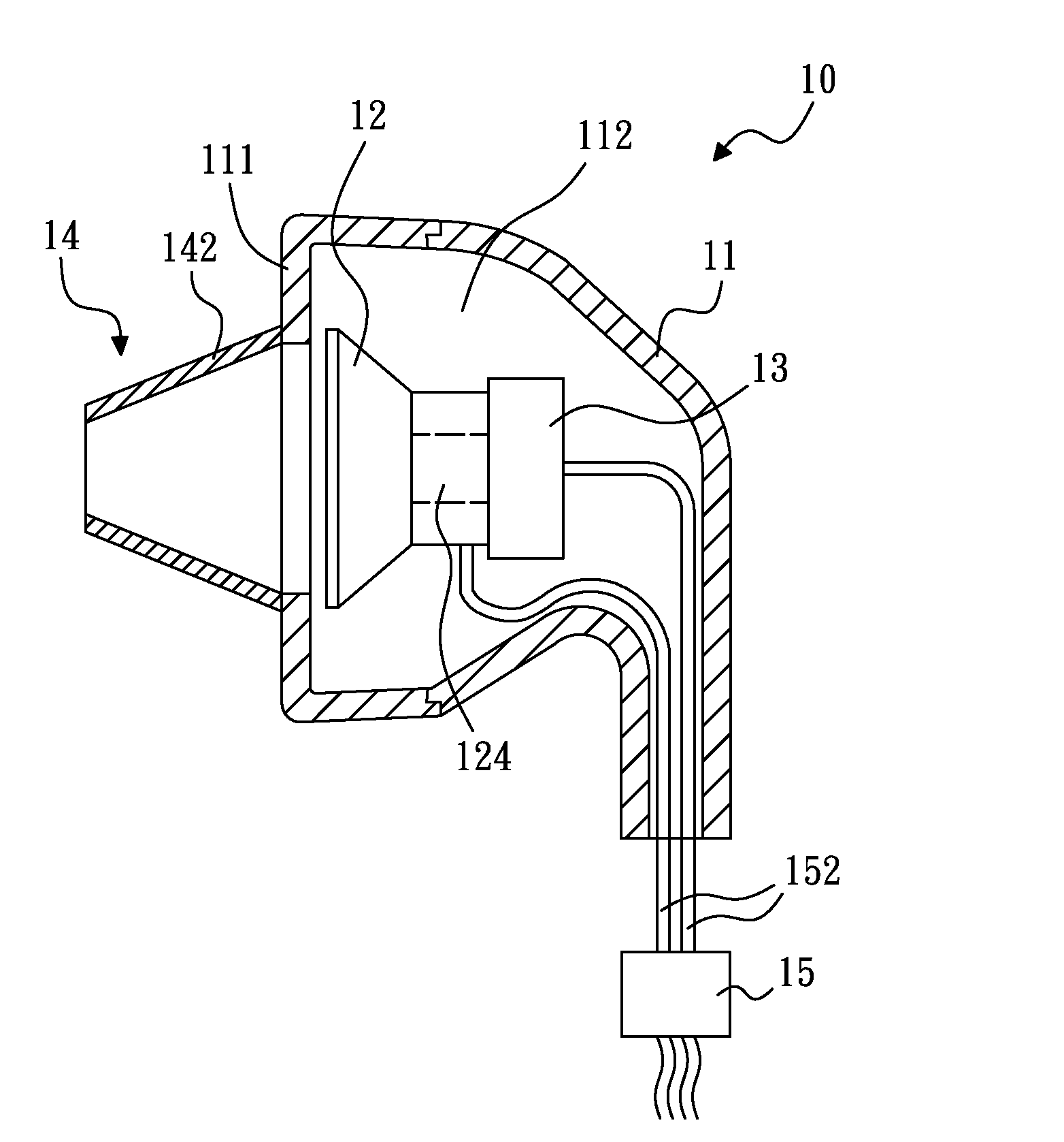
[0006]An object of the present invention is to provide an improved earpiece device, the earpiece device is incorporated with a microphone for picking up sound wave generated within an ear canal, so that the influence of the background noise can be effectively avoided.
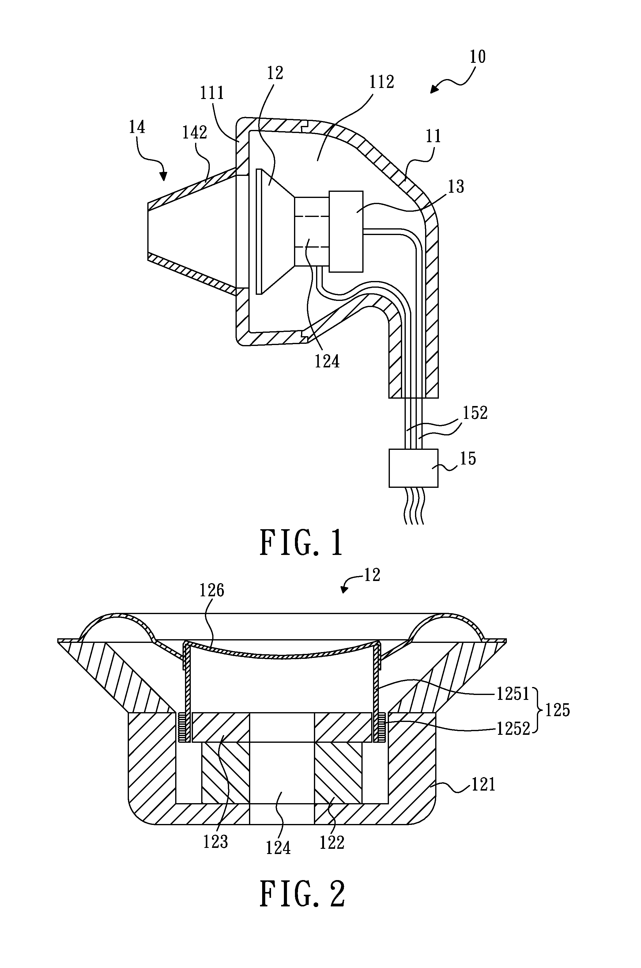
[0008]Due to the fact that the speaker is designed to have the sound transmitting hole formed thereon, the sound wave generated within the ear canal can be effectively delivered to the microphone disposed in the earpiece device. Therefore, it is unnecessary to dispose a microphone outside of the earpiece device as the conventional earpiece device.

Problems solved by technology

Therefore, it is unnecessary to dispose a microphone outside of the earpiece device as the conventional earpiece device.

Method used


Image

  • Earpiece Device with Microphone
  • Earpiece Device with Microphone
  • Earpiece Device with Microphone

Examples


Embodiment Construction

[0015]In the following detailed description of the preferred embodiments, reference is made to the accompanying drawings which form a part hereof, and in which is shown by way of illustration specific embodiments in which the invention may be practiced. In this regard, directional terminology, such as “top,”“bottom,”“front,”“back,” etc., is used with reference to the orientation of the Figure(s) being described. The components of the present invention can be positioned in a number of different orientations. As such, the directional terminology is used for purposes of illustration and is in no way limiting. On the other hand, the drawings are only schematic and the sizes of components may be exaggerated for clarity. It is to be understood that other embodiments may be utilized and structural changes may be made without departing from the scope of the present invention.

[0016]Referring to FIGS. 1 and 2, an earpiece device 10, in accordance with a first embodiment, is provided. The earp...


PUM


Abstract

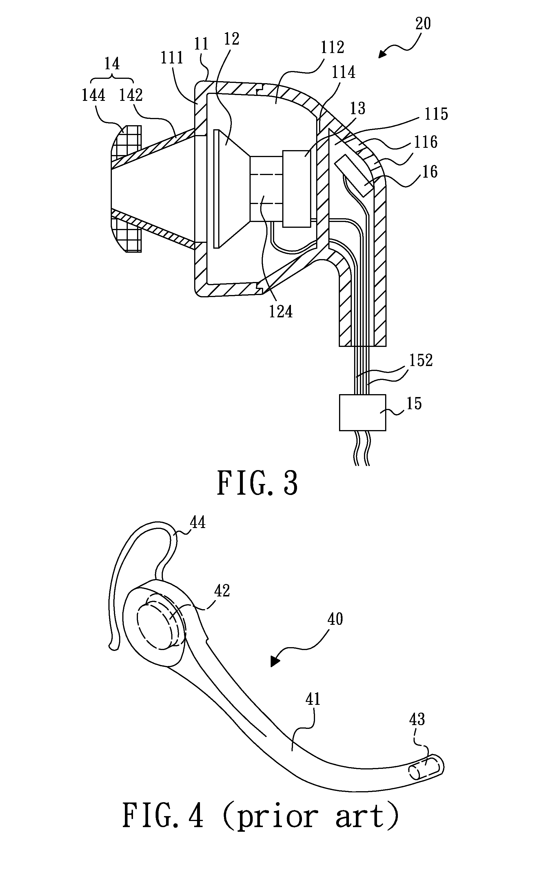
An earpiece device includes a housing having a sound output portion, a speaker and a microphone. The speaker disposed in the housing includes a diaphragm and a sound transmitting hole. The diaphragm is located between the sound output portion and the sound transmitting hole. The microphone is disposed in the housing and covers the sound transmitting hole. A sound wave generated within an ear canal would be received by the speaker and delivered through the sound transmitting hole to the microphone for pickup.

Description

BACKGROUND[0001]1. Technical Field[0002]The present invention generally relates to earpiece devices and, particularly, to an earpiece device with microphone.[0003]2. Description of the Related Art[0004]Referring to FIG. 4, a conventional earpiece device 40 includes a main body having an extension arm 41, a speaker 42, a microphone 43 and an ear-hook 44. The speaker 42 is disposed in the rear portion of the main body. The microphone 43 is secured in an end portion of the extension arm 41. When the earpiece device 40 is held on the ear of a user by the ear-hook 44 and the microphone 43 is positioned near the user's mouth, the earpiece device 40 can operatively output sound to the user's ear and pick up the user's voice.[0005]However, when the earpiece device 40 is in operation, the microphone 43 not only picks up the user's voice but also the background noise, which results in the sound quality of the microphone unsatisfactory.BRIEF SUMMARY[0006]An object of the present invention is t...

Claims


Application Information

Patent Timeline
Patent Type & Authority Applications(United States)
IPC IPC(8): H04R25/00
CPCH04R1/1016H04R1/1075H04R25/656H04R25/604H04R2201/107H04R25/04
Inventor HER, HONG-CHINGCHANG, HUNG-YUEHO, TON-KUN
Owner MERRY ELECTRONICS CO LTD
Learn More