Image Forming Apparatus

Active Publication Date: 2009-06-04
BROTHER KOGYO KK
View PDF19 Cites 25 Cited by
  • Summary
  • Abstract
  • Description
  • Claims
  • Application Information

AI Technical Summary

Benefits of technology

[0011]When the amount of mixed developer in the developer storage chamber becomes less than the predetermined amount, the notifying unit notifies the user to replace the developer receptacle so that the user can replace the developer receptacle with a new one with mixed developer remaining in the old developer receptacle. This allows a part of mixed developer within the development chamber and the developer storage chamber; more specifically, mixed developer within the developer storage chamber, to be replaced with new developer. Thereafter, the circulation mechanism again circulates developer between the development chamber and the developer storage chamber, so that mixed developer within the developer chambe

Problems solved by technology

This is particularly serious if the development device is of a type where a developer receptacle forming a developer storage chamber and a developing unit forming a development chamber are separable, because the developer receptacle is replaced with a new one for filling up toner and different color toner

Method used


Image

  • Image Forming Apparatus
  • Image Forming Apparatus
  • Image Forming Apparatus

Examples


Embodiment Construction

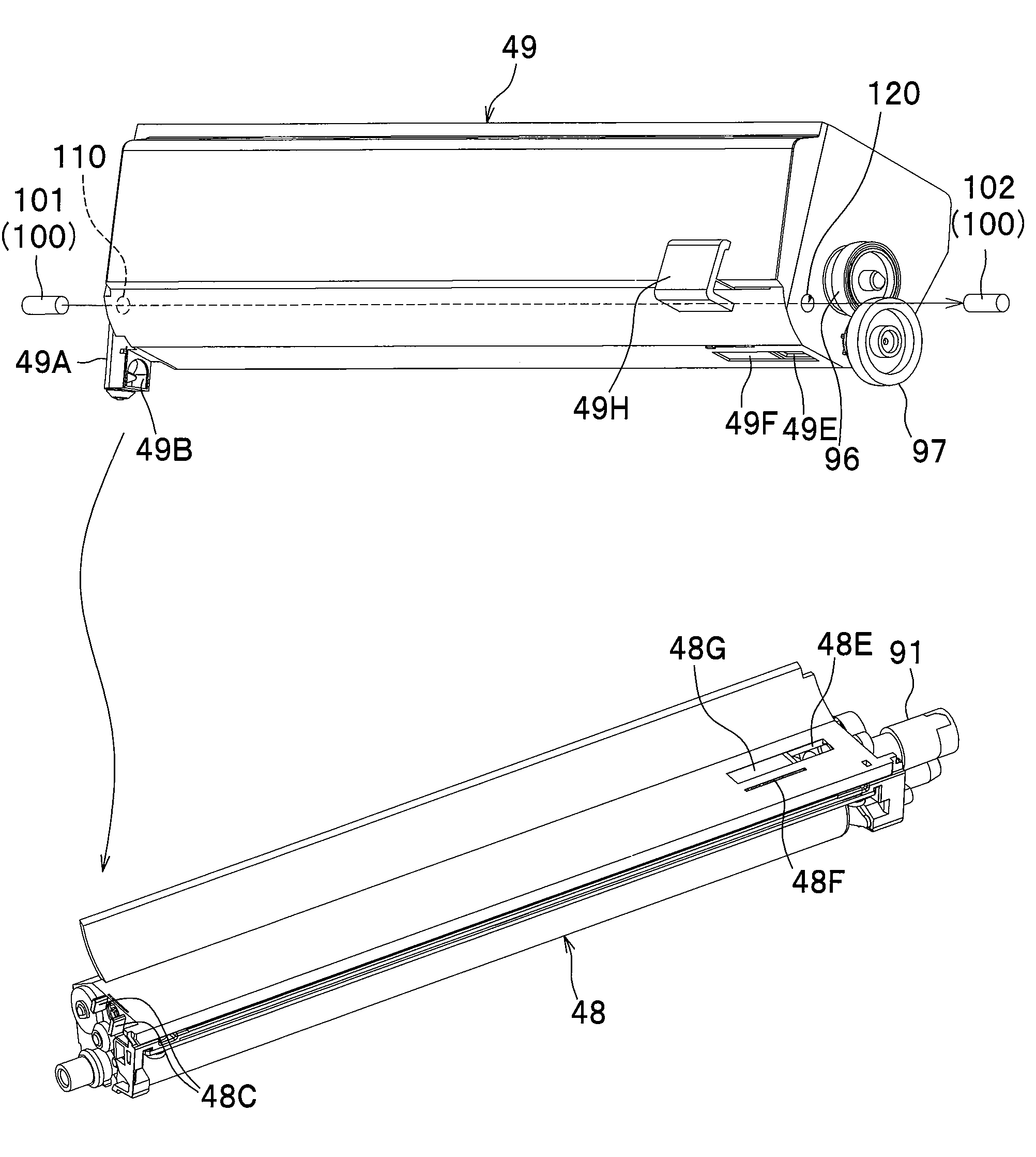
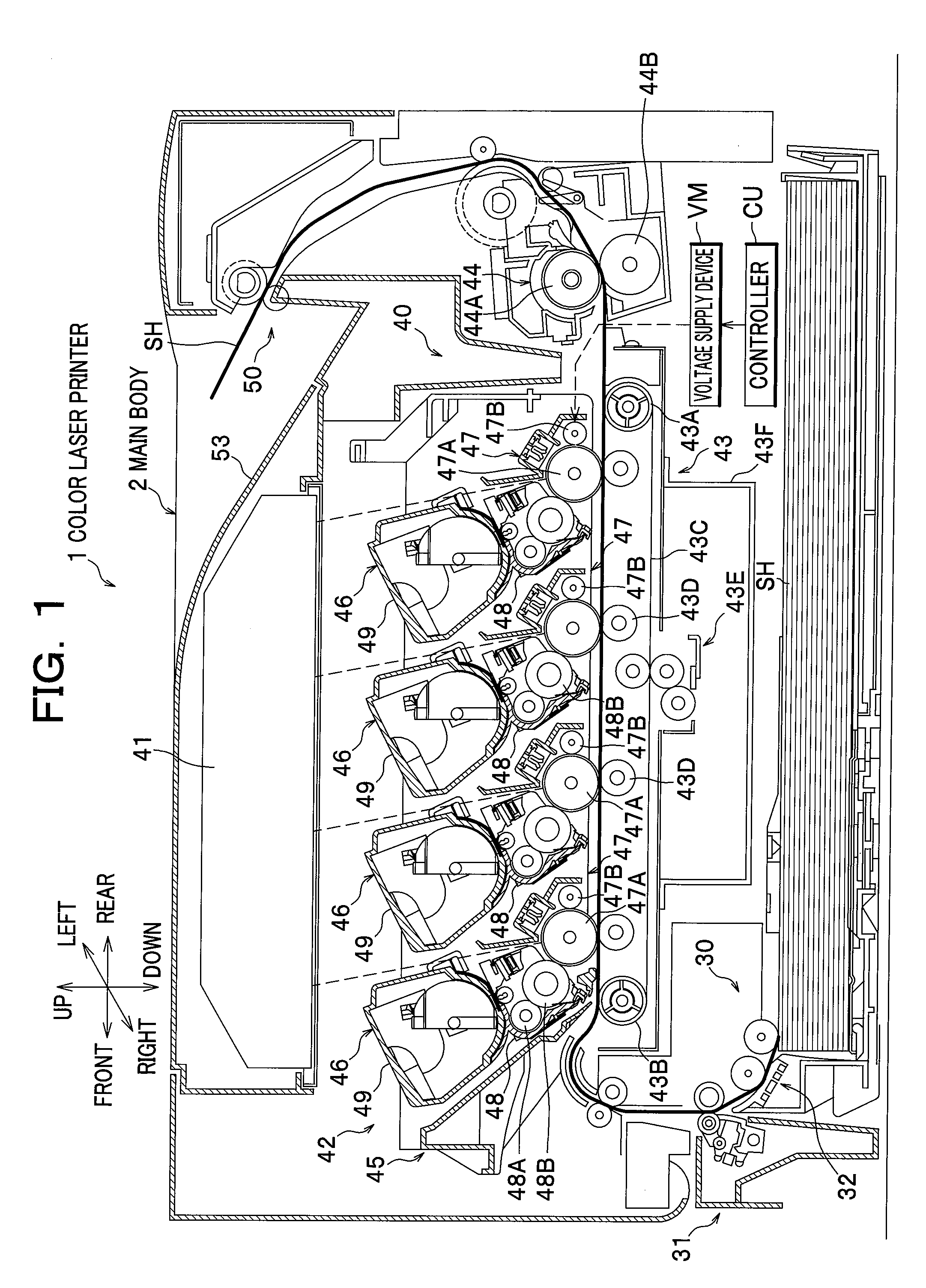
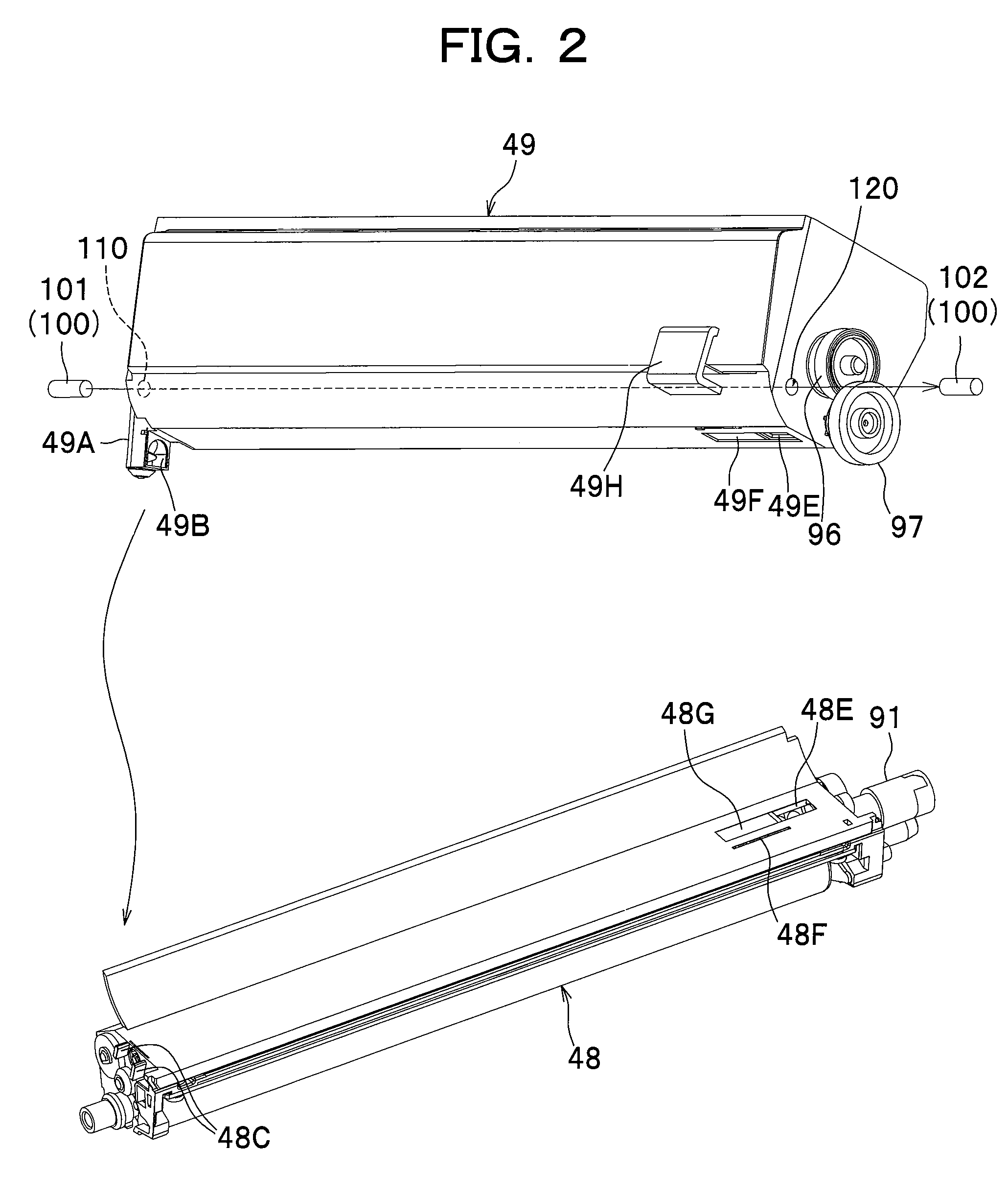
[0029]One preferred embodiment of the present invention will be described in detail with reference to the attached drawings. In the following description, the overall structure of a color laser printer as an example of an image forming apparatus according to one embodiment of the present invention will be described with reference to FIG. 1, and thereafter, a development device as an embodiment of the present invention that is assembled into the color laser printer will be described in detail.

Overall Structure of Color Laser Printer

[0030]As seen in FIG. 1, a color laser printer 1 as an embodiment of the present invention includes a sheet feed unit 30 configured to feed a recording sheet SH into a main body 2, an image forming unit 40 configured to form an image on the recording sheet SH fed from the sheet feed unit 30, and a sheet output unit 50 configured to discharge the recording sheet SH having the image thereon from the main body 2.

[0031]Directions of the color laser printer 1 a...


PUM


Abstract

An image forming apparatus includes: at least one retaining member configured to temporarily retain remaining developer remaining on a photosensitive member; a belt arranged opposite to a plurality of photosensitive members; a cleaning device collecting developer on the belt; a remaining developer collecting unit configured to cause the remaining developer retained by the retaining member to be transferred onto the belt via the photosensitive member and thereafter collected by the cleaning device; a circulation mechanism configured to circulate developer between the development chamber and the developer storage chamber; a detector detecting the amount of developer in the developer storage chamber; a determination unit configured to determine if the amount of developer in the developer storage chamber is less than a predetermined amount; and a notifying unit notifying to replace a developer receptacle when the amount of developer stored in the developer storage chamber becomes less than the predetermined amount.

Description

CROSS REFERENCE TO RELATED APPLICATION[0001]This application claims the foreign priority benefit under Title 35, United States Code, §119(a)-(d) of Japanese Patent Application No. 2007-313792 filed on Dec. 4, 2007 in the Japan Patent Office, the disclosure of which is herein incorporated by reference in its entirety.BACKGROUND OF THE INVENTION[0002]The present invention relates to an image forming apparatus equipped with a plurality of photosensitive members, and a belt arranged opposite to these photosensitive members.[0003]An image forming apparatus such as a color laser printer is generally known, which comprises a plurality of development devices each storing different color toner, a plurality of photosensitive drums each of which is supplied with toner from the corresponding development devices via a developing roller, and a belt arranged opposite to the plurality of photosensitive drums. In this image forming apparatus, a recording sheet is conveyed on the belt and passes thro...

Claims


Application Information

Patent Timeline
IPC IPC(8): G03G15/08
CPCG03G15/0815G03G15/161G03G15/553G03G2215/0141G03G15/0862G03G2215/1661G03G15/556G03G15/0856G03G2215/0888
Inventor SATO, SHOUGOSAKUMA, SUSUMU
Owner BROTHER KOGYO KK
Why Eureka
Try Eureka