Anti-shock artificial knee joint structure

Inactive Publication Date: 2009-06-04
CHENG CHIA PAO +1
View PDF4 Cites 20 Cited by
  • Summary
  • Abstract
  • Description
  • Claims
  • Application Information

AI Technical Summary

Benefits of technology

[0007]When walking with the knee joint, at the time that the limb gets contact with the ground, the weigh of a user's body falls on the knee joint, causing the pivot stop block to tightly clamp the pivot thereby preventing undesired bending of the knee joint and also transmitting the weight trough the intermediate-section linking member to the anti-shock device to alleviate the impact caused by contact with the ground, allowing a user of the knee joint to walk in a more natural and comfortable manner.

Problems solved by technology

Since the natural nee joint is of a very complicated structure, although the conventional artificial knee joint employs a mechanical structure that is effectively to substantially simulate the operation of the natural knee joint, the conventional knee joint, in consideration of structural strength and manufacturing costs, cannot exactly duplicate the operation of the natural knee joint and thus is not able to provide a user with the capability of walking in a natural way.
However, for a disabled person walking with an artificial leg, when the artificial leg is raised and put forward by the force of the thigh, the portion of the artificial leg that corresponds to a lower leg or shank of a natural leg is not subject to any control over the posture of the foot contacting the ground and the angle that the knee joint bends.
When waling in his way for a long time, the shock may cause potential damages or discomfort to the body.
Clearly enough, the conventional artificial knee joint cannot satisfy the need of the modern users, and improvement is thus required.

Method used


Image

  • Anti-shock artificial knee joint structure
  • Anti-shock artificial knee joint structure
  • Anti-shock artificial knee joint structure

Examples


Embodiment Construction

[0016]The following descriptions are of exemplary embodiments only, and are not intended to limit the scope, applicability or configuration of the invention in any way. Rather, the following description provides a convenient illustration for implementing exemplary embodiments of the invention Various changes to the described embodiments may be made in the function and arrangement of the elements described without departing from the scope of the invention as set forth in the appended claims.

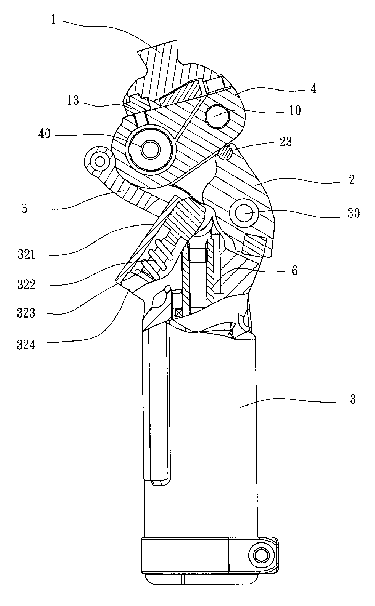
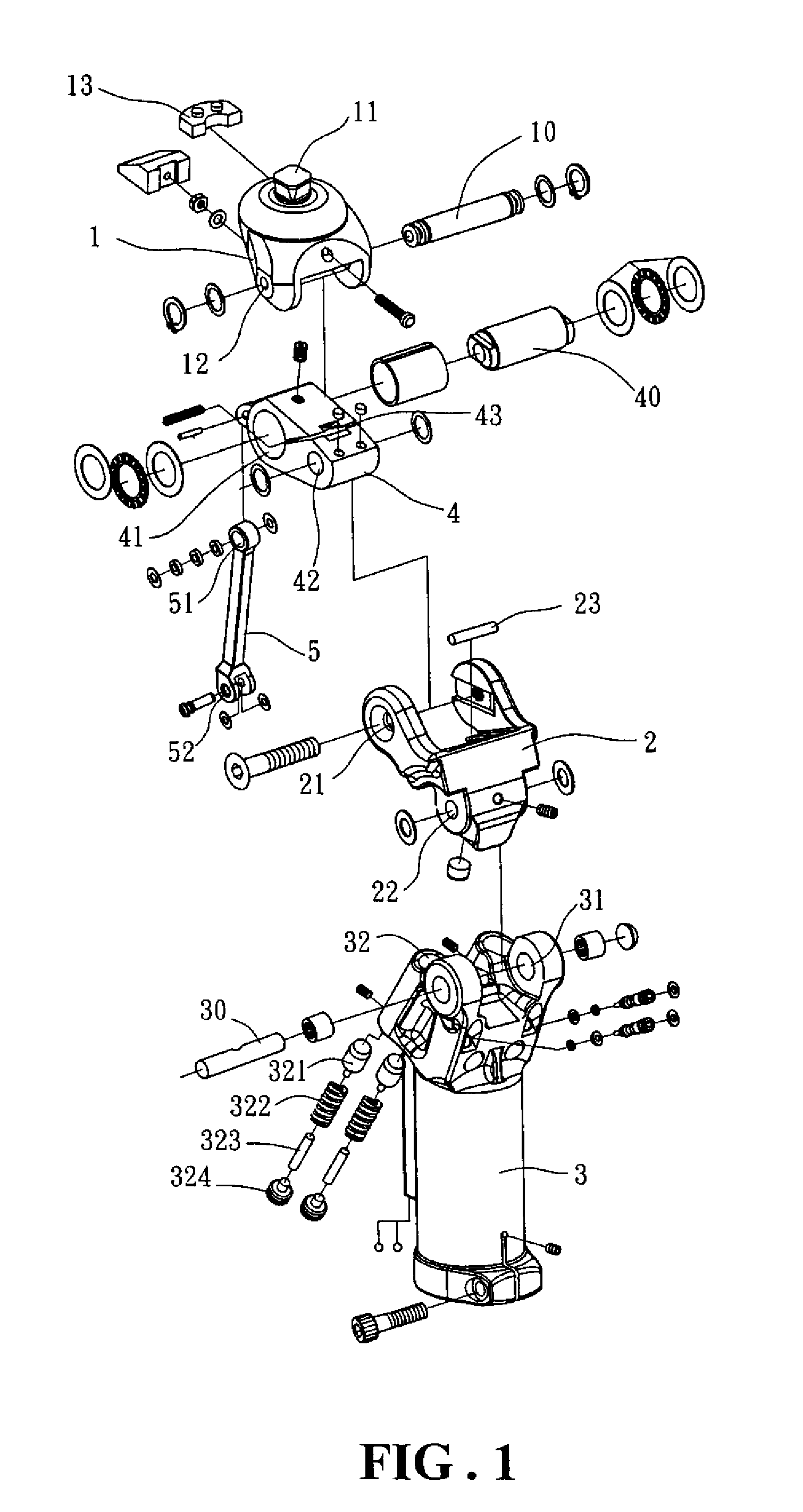
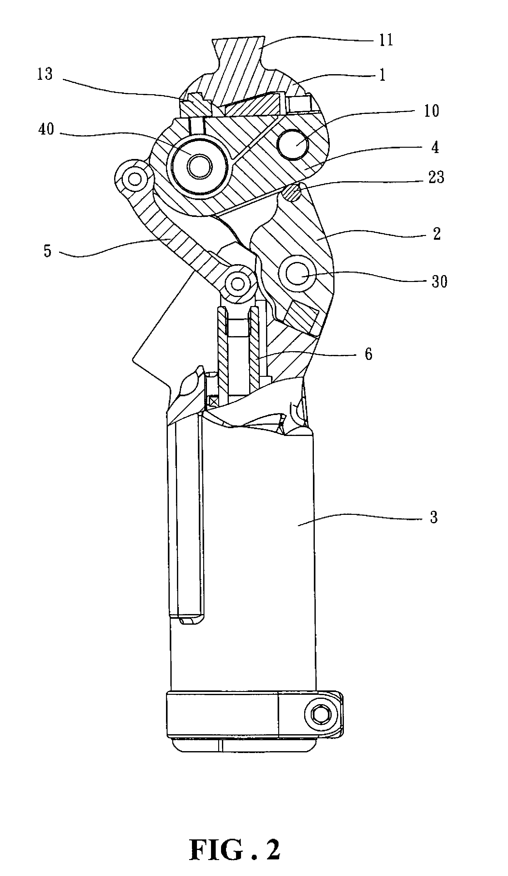
[0017]The present invention provides an anti-shock artificial knee joint of which the structure and operation will be now described in detail with reference to the attached drawings for a full understanding of the present invention. As shown in FIGS. 1-6, the anti-shock artificial knee joint in accordance with the present invention has a structure that is comprised of an upper-section linking member 1, an intermediate-section linking member 2, a lower-section pneumatic cylinder housing 3, a pivot ...


PUM


Abstract

An anti-shock artificial knee joint includes a pivot stop block forming a first pivot hole rotatably receiving therein a first pivot for bending the knee joint and a second pivot hole rotatably receiving a second pivot. A gap extending from the first pivot hole so that when the pivot stop block is subjected to an external force induced in the process of walking, the gap is reduced to secure the first pivot from rotation whereby the pivot stop block rotates about the second pivot to cause the pivot stop block to engage spring-biased pistons to thereby absorb the external force or the impact caused by the external force. The spring-biased pistons are provided with set screws to adjust the cushioning effect provided by the spring-biased pistons.

Description

BACKGROUND OF THE INVENTION[0001](a) Technical Field of the Invention[0002]The present invention relates to an anti-shock artificial knee joint structure, which uses linking members and pivots to form at least two movable jointing portions, which together with a pivot stop block and a pneumatic cylinder assembly, allows the knee joint to operate in a safe and smooth manner and constituting an anti-shock device that improves the impact acting upon the body of a disabled person walking with an artificial limb to thereby ensure a comfortable and smooth operation of the knee joint.[0003](b) Description of the Prior Art[0004]With the development and progress in medical technology, disabled persons whose legs are damaged and not allowed to walk naturally can now be rehabilitated with the waling capability by installing an artificial limb that incorporates with an artificial knee joint. The artificial knee joint of the artificial limb is a mechanical device that is designed to simulate the...

Claims


Application Information

Patent Timeline
IPC IPC(8): A61F2/62
CPCA61F2/644A61F2/68A61F2002/30359A61F2002/30434A61F2002/30497A61F2002/5003A61F2220/0041A61F2002/5075A61F2002/6818A61F2002/747A61F2220/0025A61F2220/0033A61F2002/5009A61F2002/30433A61F2002/30495A61F2/74
Inventor CHENG, CHIA-PAOWU, FU-KUO
Owner CHENG CHIA PAO
Why Eureka
Try Eureka