Molded package

Active Publication Date: 2017-11-09
DENSO CORP
View PDF0 Cites 2 Cited by
  • Summary
  • Abstract
  • Description
  • Claims
  • Application Information

AI Technical Summary

Benefits of technology

[0010]In the above molded package, the second surface of the lead frame includes a chip correspondence portion at a position corresponding to the IC mounted on the first surface. The molded resin is formed with a second surface-side opening portion on the second surface to expose the chip correspondence portion. The second surface-side opening portion is filled with a filler material so that the filler material is directly in contact with the chip correspondence portion and seals the second surface-side opening portion. The filler material has a thermal conductivity equal to or greater than that of the molded resin, and is softer than the molded resin. The chip correspondence portion has a surface shape that ensures a larger contact area with the filler material relative to a portion of the second surface of the lead frame other than the chip correspondence portion. The molded package is to be in contact with an external member located outside of the molded package at the filler material.
[0

Problems solved by technology

For example, in a case where the molded package is provided as a humidity sensor or the like, the external member to which the heat is conducted is like

Method used


Image

  • Molded package
  • Molded package
  • Molded package

Examples


Example

First Embodiment

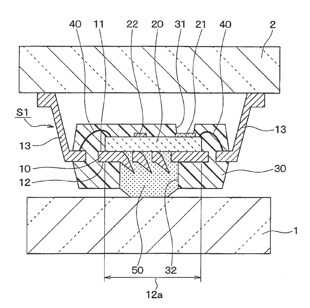
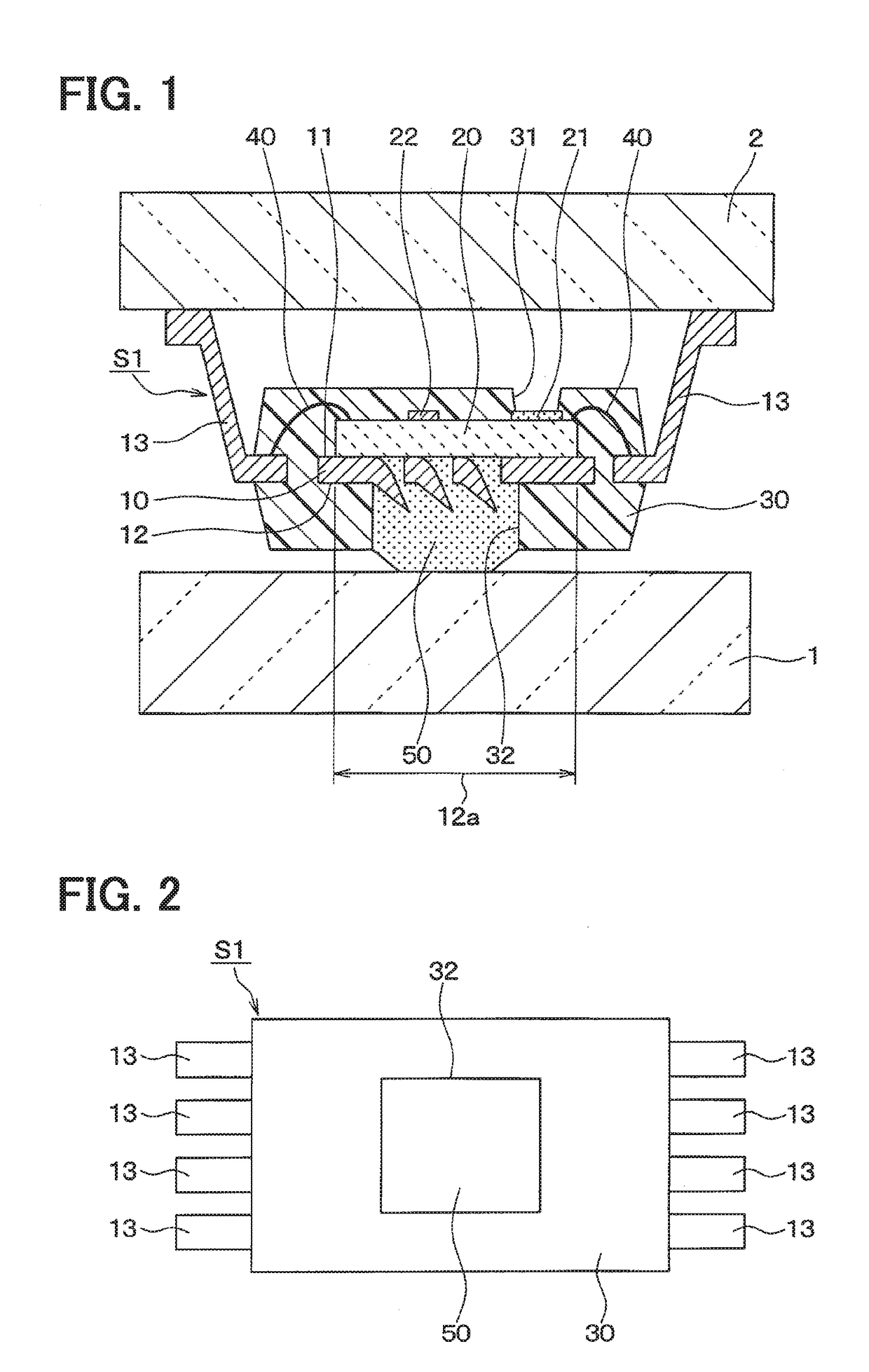
[0022]A molded package S1 according to the first embodiment of the present disclosure will be described with reference to FIGS. 1 and 2. The molded package S1 of the present embodiment is, for example, used as a humidity sensor of a vehicle air conditioning apparatus.

[0023]Specifically, an external member 1 located outside of the molded package S1 is glass, such as a windshield of a vehicle. The molded package S1 is attached to the external member 1 and detects the humidity inside of the passenger compartment and the temperature of the external member 1.

[0024]The molded package S1 of the present embodiment includes, as main components, a metal lead frame 10, an IC chip 20, and a molded resin 30. The lead frame 10 has a first surface 11 and a second surface 12 opposite to the first surface 11. The IC chip 20 is mounted on the first surface 11 of the lead frame 10. The molded resin 30 encapsulates the first surface 11 and the second surface 12 of the lead frame 10 with...

Example

Second Embodiment

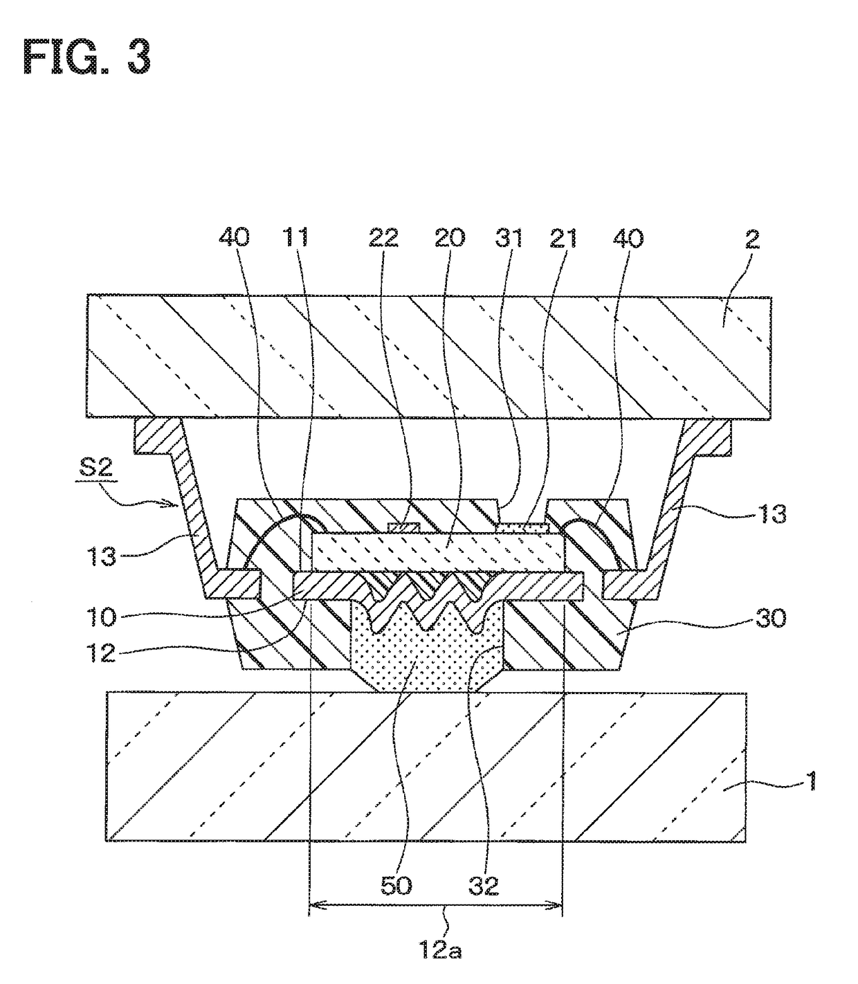
[0058]A molded package S2 according to a second embodiment of the present disclosure will be described with reference to FIG. 3. In the present embodiment, the molded package S2 is different from the molded package S1 of the first embodiment as the surface shape of the chip correspondence portion 12a is modified, and thus the difference will be mainly described hereinafter.

[0059]Also in the present embodiment, the chip correspondence portion 12a has a rough surface that is provided by forming the portion of the lead frame 10 corresponding to the chip correspondence portion 12a into a plate shape having projections and recesses in cross section, as the surface shape that can increase the contact area with the filler material 50.

[0060]In the first embodiment, the rough surface is formed as the surface with the fine splits. In the present embodiment, on the other hand, the rough surface is provided by a waved plate shape having substantially a uniform plate thickness.

[...

Example

Third Embodiment

[0062]A molded package S3 according to a third embodiment of the present disclosure will be described with reference to FIG. 4. In the present embodiment, the molded package S3 is different from the molded package S2 of the second embodiment as the surface shape of the chip correspondence portion 12a is modified, and thus the difference will be mainly described hereinafter.

[0063]The chip correspondence portion 12a of the second embodiment described above has the rough surface having substantially the uniform thickness, which is made by the pressing. In the present embodiment, on the other hand, the rough surface of the chip correspondence portion 12a is formed by partially differentiating the thickness of the chip correspondence portion 12a by a mold processing. Also in the present embodiment, the similar effects to the second embodiment can be expected.

[0064]Also in the second embodiment and the third embodiment described above, the projections of the rough surface ...


PUM


Abstract

A molded package includes an IC chip mounted on a first surface of a lead frame, and a molded resin encapsulating the lead frame together with the IC chip. The molded resin has a second surface-side opening portion that is formed to expose a chip correspondence portion of a second surface of the lead frame corresponding to the IC chip. A filler material is filled in the second surface-side opening portion. The filler material has a thermal conductivity equal to or greater than that of the molded resin and is softer than the molded resin. The chip correspondence portion has a rough surface with fine splits so as to increase a contact area with the filler material, and the filler material is in contact with the external member.

Description

CROSS REFERENCE TO RELATED APPLICATION[0001]This application is based on Japanese Patent Application No. 2014-143257 filed on Jul. 11, 2014, the disclosure of which is incorporated herein by reference.TECHNICAL FIELD[0002]The present disclosure relates to a molded package in which a lead frame having an IC chip thereon is encapsulated with a molded resin, and particularly relates to improvement of thermal conduction of the molded package to an external member outside of the molded package.BACKGROUND ART[0003]As such a type of molded package, it has been conventionally proposed a molded package that includes a metal lead frame, an IC chip mounted on a first surface of the lead frame, and a molded resin encapsulating the lead frame together with the IC chip while exposing a second surface of the lead frame from the molded resin (for example, see patent literature 1).[0004]This type of the molded package generally realizes a thermal conduction with an external member, such as a printed...

Claims


Application Information

Patent Timeline
IPC IPC(8): H01L23/29H01L23/50H01L23/31H01L23/48
CPCH01L23/49582H01L23/49586H01L23/29H01L23/31H01L23/48H01L2924/1815H01L2224/32245H01L2224/48091H01L2224/48247H01L2224/73265H01L2224/83385H01L23/50H01L2924/181H01L23/42H01L23/49503H01L23/3737H01L23/3107H01L23/49568H01L23/49555H01L2924/00012H01L2924/00014H01L2924/00
Inventor ARIKI, TOMOHIDE
Owner DENSO CORP
Why Eureka
Try Eureka