Vehicle-mounted battery apparatus

Active Publication Date: 2019-06-27
TOYOTA JIDOSHA KK
View PDF3 Cites 2 Cited by
  • Summary
  • Abstract
  • Description
  • Claims
  • Application Information

AI Technical Summary

Benefits of technology

The present disclosure is about a vehicle-mounted battery apparatus that can suppress unusual noise. The apparatus includes a battery pack, a smoke exhaust duct, and a check valve. The check valve has a shock absorbing member to prevent impact and noise caused by the movement of the valve body and valve seat. The apparatus also includes a pivot shaft and a bearing to prevent the pivot shaft from coming off. The shock absorbing member is a porous material that can hold foreign matter and prevent it from entering and scattering in the system. The technical effects of this invention are to suppress noise and prevent damage to the vehicle-mounted battery apparatus.

Problems solved by technology

As a result of this, a valve body may be lifted up to hit against a valve seat and thereby generate unusual noise.

Method used


Image

  • Vehicle-mounted battery apparatus
  • Vehicle-mounted battery apparatus
  • Vehicle-mounted battery apparatus

Examples


first embodiment

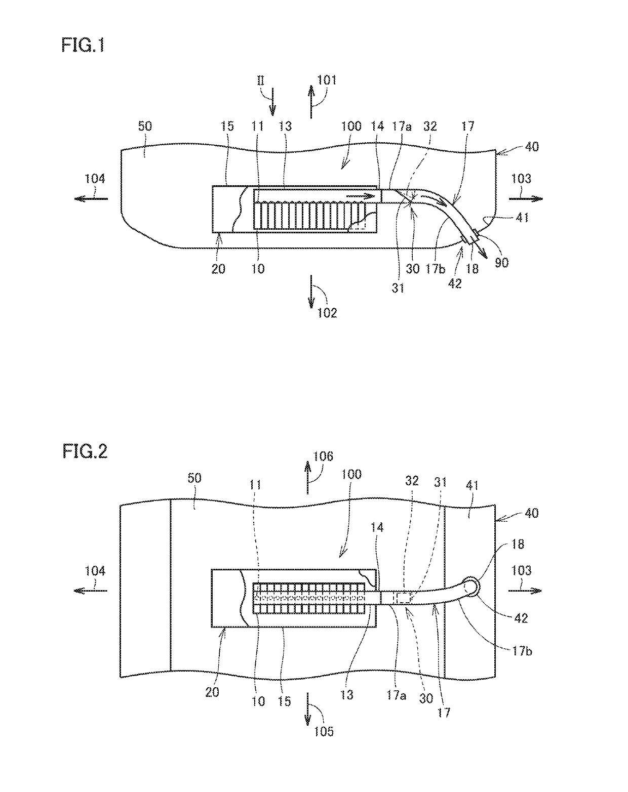
[0027]FIG. 1 is a side view of a vehicle-mounted battery apparatus according to a first embodiment. FIG. 2 is a plan view of the vehicle-mounted battery apparatus as seen in the direction indicated by arrow II in FIG. 1. As shown in FIGS. 1 and 2, vehicle-mounted battery apparatus 100 according to the present embodiment is mounted in a vehicle 40.

[0028]In FIGS. 1 and 2, arrow 101 indicates the upward direction of vehicle 40, arrow 102 indicates the downward direction of vehicle 40, arrow 103 indicates the rightward direction of vehicle 40, arrow 104 indicates the leftward direction of vehicle 40, arrow 105 indicates the rearward direction of vehicle 40, and arrow 106 indicates the frontward direction of vehicle 40.

[0029]Vehicle-mounted battery apparatus 100 includes a battery pack 20 and a smoke exhaust duct 17 connected to battery pack 20 for discharging gas to the outside of the vehicle. Battery pack 20 includes a battery cell 10 constructed by a lithium-ion cell, a casing 15 whic...

second embodiment

[0057]FIG. 8 is an exploded perspective view of a smoke exhaust duct of a vehicle-mounted battery apparatus according to a second embodiment. FIG. 9 is a cross-sectional view along line IX-IX in FIG. 8. As shown in FIGS. 8 and 9, in the smoke exhaust duct of the vehicle-mounted battery apparatus according to the second embodiment, ribs 31a are disposed in hole 33. In this example, ribs 31a in a cross shape are disposed in hole 33. Alternatively, ribs 31a in an X shape may be disposed in hole 33. In this example, two ribs 31a are shaped to intersect each other. Alternatively, multiple ribs 31a may be shaped not to intersect each other. Still alternatively, a single rib 31a may be disposed.

[0058]The second embodiment differs from the first embodiment in the structure of bearing(s) 38. According to the first embodiment, two bearings 38 spaced from each other by a predetermined distance support a single pivot shaft 32a. According to the second embodiment, a single bearing 38 supports a ...

third embodiment

[0060]FIG. 10 is a plan view of a valve body for use in a vehicle-mounted battery apparatus according to a third embodiment. FIG. 10 shows a surface of valve body 32 that is to face valve seat 31. As shown in FIG. 10, a shock absorbing member 39 is disposed on an outer peripheral portion of valve body 32 according to the third embodiment. Shock absorbing member 39 is disposed on only the outer peripheral portion, and therefore, the amount of shock absorbing member 39 used for the valve body can be reduced. Further, the total mass of shock absorbing member 39 and valve body 32 can be made smaller than those in the first and second embodiments.


PUM


Abstract

A vehicle-mounted battery apparatus to be mounted in a vehicle includes: a battery pack, the battery pack including a battery cell, the battery cell including a gas exhaust portion configured to discharge internal gas; a smoke exhaust duct connected to the battery pack and configured to discharge gas to an outside of the vehicle; and a check valve disposed in the smoke exhaust duct and configured to block flow of gas from the outside of the vehicle toward the battery pack. The check valve includes: a valve seat disposed in the smoke exhaust duct and having a hole; a valve body configured to be seated on the valve seat to cover the hole; and a shock absorbing member disposed between the valve body and the valve seat to alleviate impact of the valve body against the valve seat.

Description

[0001]This nonprovisional application is based on Japanese Patent Application No. 2017-250782 filed on Dec. 27, 2017 with the Japan Patent Office, the entire contents of which are hereby incorporated by reference.BACKGROUNDField[0002]The present disclosure relates to a battery apparatus to be mounted in a vehicle (also referred to herein as “vehicle-mounted battery apparatus”).Description of the Background Art[0003]Vehicle-mounted battery apparatuses are disclosed for example in Japanese Patent Laying-Open Nos. 2017-50055 and 2017-91950. Respective vehicle-mounted battery apparatuses structured as disclosed in these documents are each equipped with a smoke exhaust duct for discharging gas from inside a battery. The smoke exhaust duct is connected to extend to the outside of the vehicle so that gas can be discharged to the outside of the vehicle.SUMMARY[0004]In the structures disclosed in the above-identified patent documents, air may flow from the outside of the vehicle into the smo...

Claims


Application Information

Patent Timeline
IPC IPC(8): H01M2/12H01M2/10B60L50/64
CPCH01M2/1264H01M2/1077B60L50/64B60K6/28B60Y2200/91B60Y2200/92B60Y2400/112H01M2220/20H01M50/249B60K1/04Y02T10/70Y02E60/10H01M50/30H01M50/394
Inventor OKI, ATSUSHIKATAYAMA, JUNTA
Owner TOYOTA JIDOSHA KK
Why Eureka
Try Eureka