
Display device

a display device and display technology, applied in optics, instruments, electrical equipment, etc., can solve the problems of insufficient contrast ratio in 2d mode or 3d mode for many applications, and achieve good contrast ratio characteristics

Inactive Publication Date: 2009-06-11
KONINKLIJKE PHILIPS ELECTRONICS NV
View PDF8 Cites 10 Cited by
  • Summary
  • Abstract
  • Description
  • Claims
  • Application Information

AI Technical Summary

Benefits of technology

[0004]It is therefore an object of the present invention to provide a display device of the initially mentioned kind, where good contrast ratio characteristics can be achieved regardless of in which operation mode the lens layer is used.
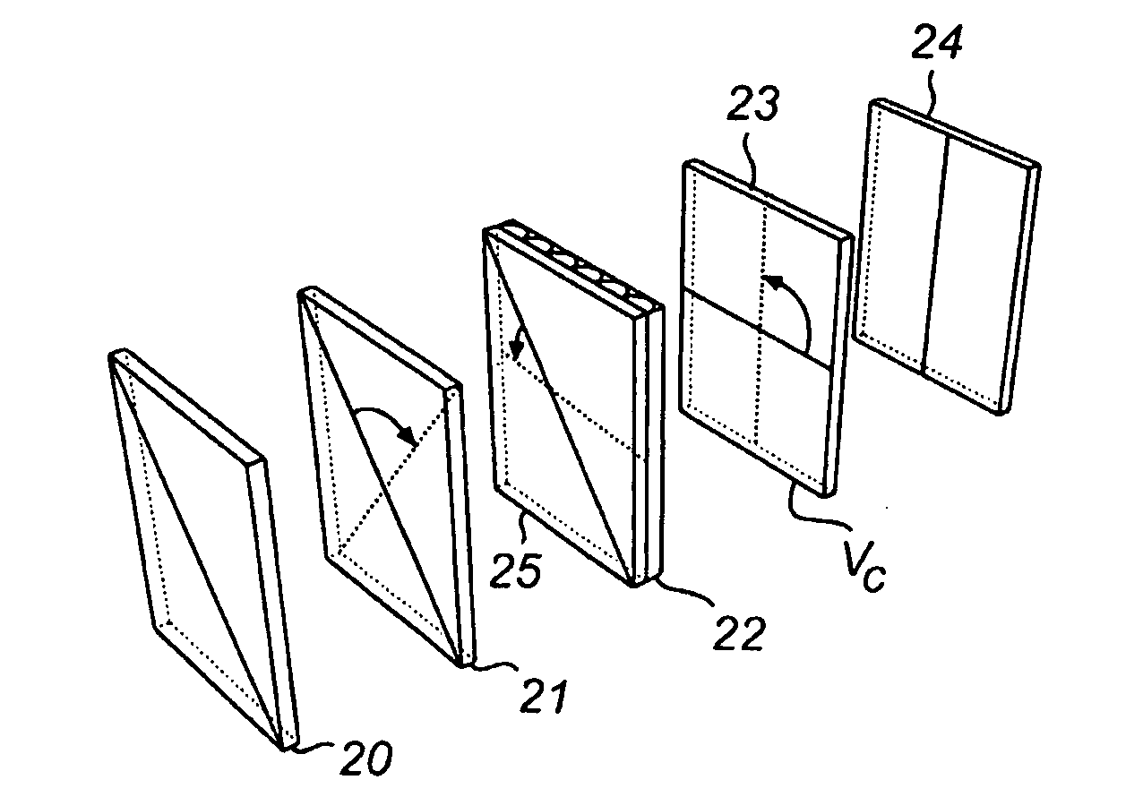
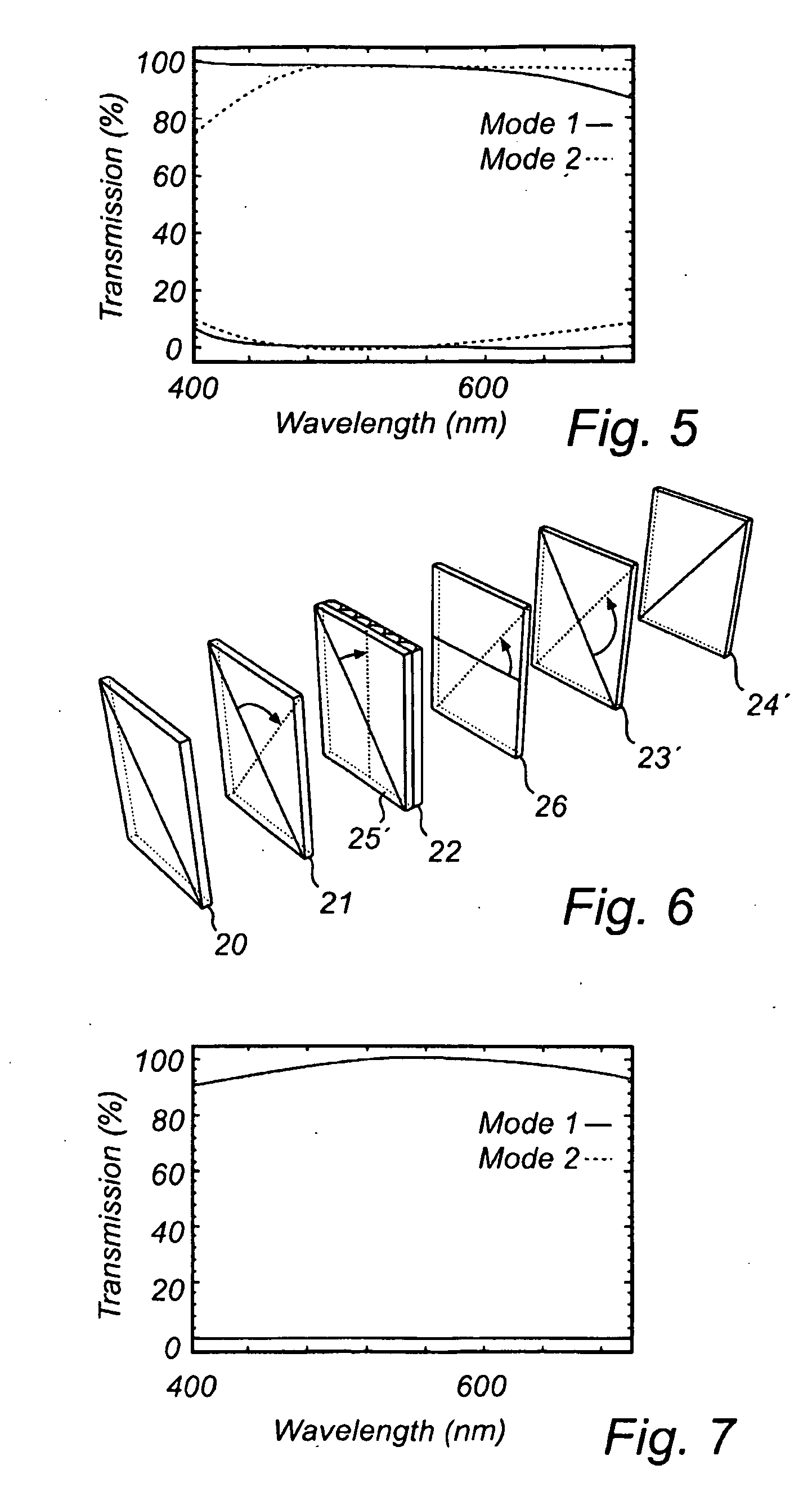
[0007]The added birefringent compensation layer provides a twist in the opposite direction as compared to the rotator layer, and has shown to compensate for any ellipticity introduced by the rotator layer in such a way that two layers, when taken together, provide a substantially improved contrast ratio for the display.
[0008]This effect may be provided by letting the retardation value of the birefringent compensation layer be substantially equal to the retardation value of the rotator layer.
[0011]In a preferred embodiment, also the retardation value of the switchable birefringent layer is substantially equal to the retardation value of the LC layer. This also provides an improved effect to the contrast ratio.

Problems solved by technology

A problem with such a display is that the contrast ratio in either the 2D mode or the 3D mode is insufficient for many applications.

Method used


Image

  • Display device
  • Display device
  • Display device

Examples


Embodiment Construction

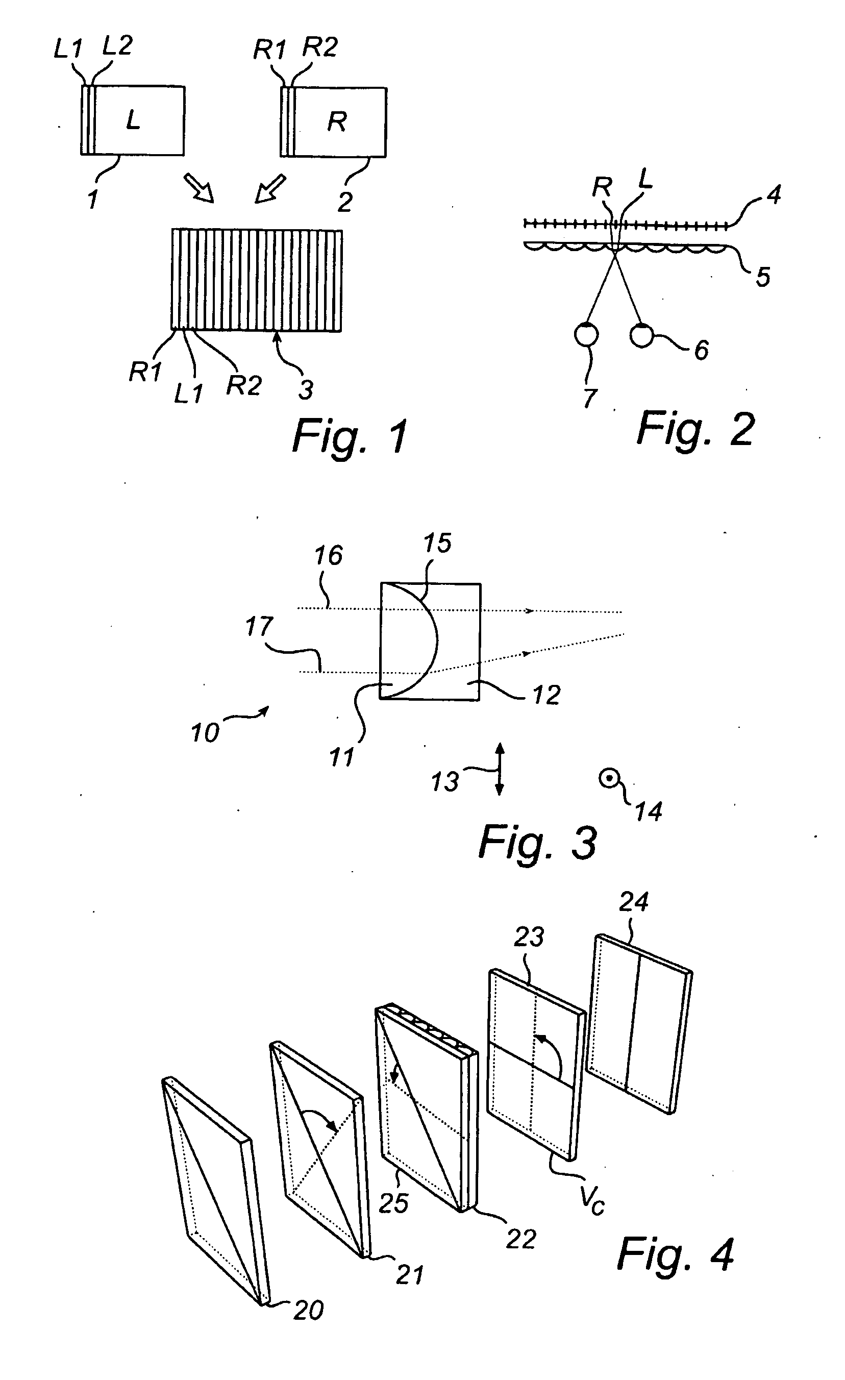
[0024]FIGS. 1 and 2 illustrate schematically a concept for obtaining an autostereoscopic image. By an autostereoscopic image is meant an image that to a user appears to be 3-dimensional, without the use of special glasses.

[0025]With reference to FIG. 1, a first image 1 is intended to be displayed to the left eye of a user, whereas a second image 2 is intended to be displayed to the fight eye of a user. Such images may be obtained e.g. by photographing an object with two offset cameras, much, like the human eyes. It is of course possible to obtain such images in many other ways.

[0026]From the first and second images 1, 2 a composite image 3 may be obtained by interleaving thin vertical slices L1, L2, etc.; R1, R2, etc. from the first and second images 1, 2 in an ordered manner (from left to right: leftmost slice from second image, leftmost slice from first image, second leftmost slice from second image etc.). The composite image may be displayed e.g. using a liquid crystal display (L...


PUM

PropertyMeasurementUnit
azimutal angleaaaaaaaaaa

Abstract

The present invention relates to a display device with a birefringent lens system having cylindrical lenses, extending in a main direction. The polarisation of light modulated by a LC layer is twisted by a rotator layer (25′) in order to be perpendicular or parallel with this main direction. A birefringent compensation layer (26) is used to remove any ellipticity introduced by the rotator layer (25′). This provides improved contrast when the display device is used e.g. in a switchable 2D / 3D display.

Description

FIELD OF THE INVENTION[0001]The present invention relates to a display device comprising a controllable LC (liquid crystal) layer, a birefringent lens layer, comprising a number of cylindrical lenses, extending in a main direction, and a rotator layer providing a polarisation twist for rotating the polarisation direction of light rays, received from the LC layer, in such a way that it is parallel with or perpendicular to the main direction, the lens layer refracting said light rays differently depending on their direction of polarisation; and a switchable birefringent layer, receiving light rays from the lens layer and providing a variable amount of polarising twist to these rays in order to select an operation mode for the birefringent lens layer.BACKGROUND OF THE INVENTION[0002]Such a device is disclosed in WO, A2, 03 / 015424 and results in a display that is switchable between a 2D mode and a 3D mode. A rotator layer may be used to adapt commercially available controllable LC layer...

Claims


Application Information

Patent Timeline
Patent Type & Authority Applications(United States)
IPC IPC(8): G02F1/13363G02F1/1333G02B30/28
CPCG02B27/2214G02B27/26G02F1/133526H04N13/0456H04N13/0404H04N13/0454G02F2203/07H04N13/305H04N13/359H04N13/361G02B30/25G02B30/28G02F1/1335H04N13/00G02B30/27
Inventor ROOSENDAAL, SANDER J.VAN BERKEL, CORNELIS
Owner KONINKLIJKE PHILIPS ELECTRONICS NV
Learn More