Dual stripper rubber cartridge with leak detection

Inactive Publication Date: 2009-06-18
SMITH INT INC
View PDF4 Cites 60 Cited by
  • Summary
  • Abstract
  • Description
  • Claims
  • Application Information

AI Technical Summary

Benefits of technology

[0009]In one aspect, embodiments disclosed herein relate to a method to detect leaks in a rotating control device, the method including positioning a leak detection device in communication with a chamber loca

Problems solved by technology

Absent any flow control schemes, fluids from such ruptured formations may blow out of the wellbore like a geyser and spew hydrocarbons and other undesirable fluids (e.g., H2S gas) into the atmosphere.
However, under certain circumstances, the drill bit will encounter pockets of pressurized formations and will cause the wellbore to “kick” or experience a rapid increase in pressure.
Because formation kicks are unpredictable and would otherwi

Method used


Image

  • Dual stripper rubber cartridge with leak detection
  • Dual stripper rubber cartridge with leak detection
  • Dual stripper rubber cartridge with leak detection

Examples


Embodiment Construction

[0019]In one aspect, embodiments disclosed herein relate to apparatus and methods for wellbore drilling. More particularly, the present disclosure relates to apparatus and methods for leak detection in a dual stripper rotating control drilling device.

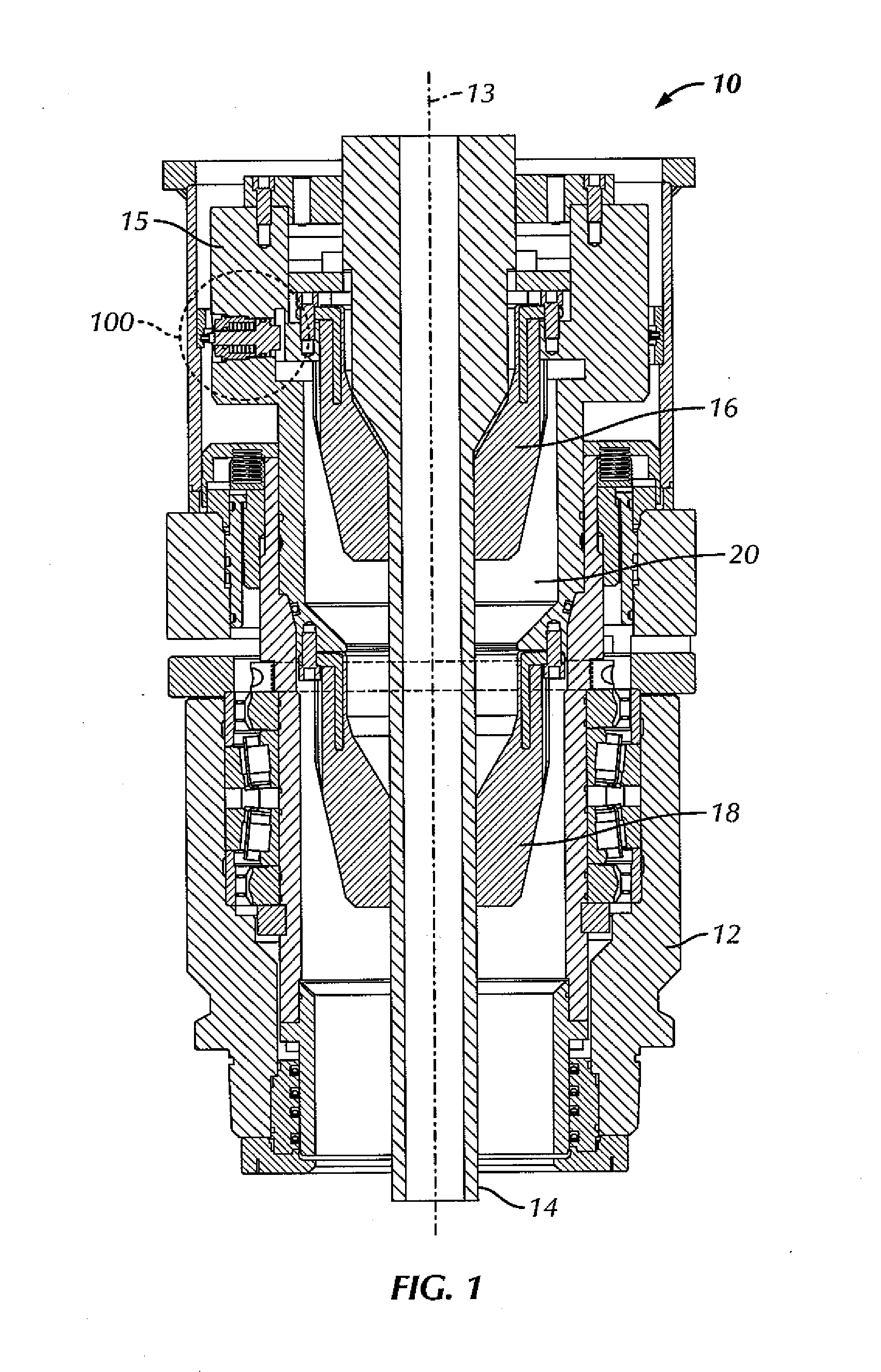
[0020]Referring to FIG. 1, a section view of a rotating control drilling device 10 is shown in accordance with embodiments of the present disclosure. Rotating control drilling device 10 includes a body 12 having a central axis 13 through which a drillstring 14 passes. An upper sealing element 16 and a lower sealing element 18 seal about drillstring 14 forming a chamber 20 therebetween. Chamber 20 may trap pressure between upper sealing element 16 and lower sealing element 18. Further, rotating control device 10 includes a bearing package 15 within body 12 which allows upper sealing element 16 and lower sealing element 18 to rotate about central axis 13 along with drillstring 14 during operation.

[0021]Rotating control drilling device 10 ...


PUM


Abstract

A rotating control drilling device includes an upper sealing element and a lower sealing element positioned around a drillstring and forming a chamber therebetween and a leak detection device. The leak detection device includes a piston in communication with the chamber, a magnet disc disposed on an end of the piston, and a plurality of magnetic sensors arranged in a magnetic sensing ring around the rotating control drilling device. Upon reaching a selected critical pressure in the chamber, a spring is configured to compress as the magnet disc is positioned proximate to the plurality of magnetic sensors. Furthermore, a method to detect leaks in a rotating control device includes positioning a leak detection device in communication with a chamber located between upper and lower sealing elements and signaling with the leak detection device when a pressure of the chamber exceeds a selected critical pressure.

Description

BACKGROUND[0001]1. Field of the Disclosure[0002]Embodiments disclosed herein relate generally to apparatus and methods for wellbore drilling. More particularly, the present disclosure relates to apparatus and methods for leak detection in a rotating control drilling device.[0003]2. Background Art[0004]Wellbores are drilled deep into the earth's crust to recover oil and gas deposits trapped in the formations below. Typically, these wellbores are drilled by an apparatus that rotates a drill bit at the end of a long string of threaded pipes known as a drillstring. Because of the energy and friction involved in drilling a wellbore in the earth's formation, drilling fluids, commonly referred to as drilling mud, are used to lubricate and cool the drill bit as it cuts the rock formations below. Furthermore, in addition to cooling and lubricating the drill bit, drilling mud also performs the secondary and tertiary functions of removing the drill cuttings from the bottom of the wellbore and ...

Claims


Application Information

Patent Timeline
IPC IPC(8): G01M3/28E21B21/08
CPCE21B21/08E21B47/1025E21B33/085E21B47/117E21B33/068E21B47/06
Inventor LEDUC, TRUNGLEWIS, RUSSELL
Owner SMITH INT INC
Why Eureka
Try Eureka