
Wing and method for reducing effects of propeller airflow on lift distribution

Active Publication Date: 2009-06-18
AIRBUS OPERATIONS GMBH
View PDF6 Cites 21 Cited by
  • Summary
  • Abstract
  • Description
  • Claims
  • Application Information

AI Technical Summary

Benefits of technology

[0006]This may provide for a suitable modification of a wing that results in a reduction of the induced drag that is increased by at least one propeller slipstream that flows onto the wing.
[0008]By targeted compensation of the lift increase or lift reduction caused by the propeller slipstream effects, a balanced lift distribution occurs at a specific operating point, so that at least in this region, there is no increase in the induced drag.
[0010]This may also provide for a method for reducing the induced drag that is increased as a result of at least one propeller slipstream flowing onto a wing, as stated in the independent method-related claim. Finally, this may also provide for an aircraft comprising a wing according to the above explanations.

Problems solved by technology

As a result of such unevenness in the lift distribution the induced drag of the wing is increased.
However, in the case of non-separated airflow the influence on the wing lift distribution is small.

Method used


Image

  • Wing and method for reducing effects of propeller airflow on lift distribution
  • Wing and method for reducing effects of propeller airflow on lift distribution

Examples


Embodiment Construction

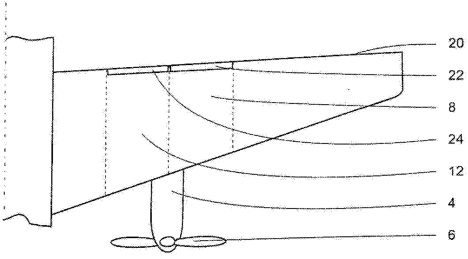
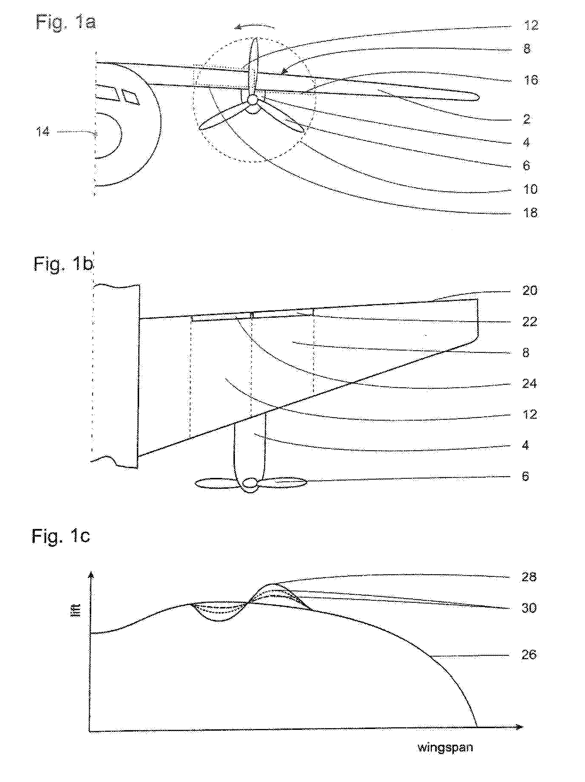
[0015]FIG. 1a shows a wing 2 on which a propulsion unit 4 with a propeller 6 is arranged. The direction of rotation of the propeller is mathematically positive in the drawing plane, in other words the propeller rotates counterclockwise. On the wing 2, the first region 8 is marked, which is situated behind the right-hand half of the propeller plane 10; as is the second region 12, which is situated behind the left-hand half of the propeller plane 10. Due to the direction of rotation of the propeller 6, an upwards directed flow component acts on the first region 8, and a downwards directed flow component acts on the second region 12. These two vertical flow components are superimposed in the horizontal main flow, which is essentially present in a longitudinal direction parallel to the longitudinal axis 14 of the aircraft.

[0016]In the drawing plane of 1a a negative twist in the first region 8 is shown by a dotted line 16; in the second region the positive twist is shown by the dotted li...


PUM


Abstract

A wing for an aircraft includes a non-balanced lift gradient because as a result of at least one propeller slipstream flowing onto the wing the induced drag of the wing is increased. To reduce the increased induced drag, the wing comprises a first region with a reduced local wing camber and / or reduced local twist, and a second region with an increased local wing camber and / or increased local twist. The first region is defined as a wing surface situated downstream of the propeller slipstream, upstream of which wing surface the blades of the propeller move upwards. The second region is defined as a wing surface situated downstream of the propeller slipstream, upstream of which wing surface the blades of the propeller move downwards.

Description

CROSS-REFERENCE TO RELATED APPLICATIONS[0001]This application claims the benefit of the filing date of U.S. Provisional Patent Application No. 61 / 007,654 filed Dec. 14, 2007, the disclosure of which is hereby incorporated herein by reference.BACKGROUND OF THE INVENTION[0002]The invention relates to a wing and a method for reducing the induced drag that is increased as a result of at least one propeller slipstream flowing onto a wing.[0003]With propeller-driven aircraft there is an aerodynamic interaction between the propeller slipstream and the flow around the wing. This is of great significance in particular if the propeller / s is / are situated in front of the wing, for example in turboprop aircraft, e.g. the A400M. During operation propellers not only produce a thrust-generating flow component that acts in longitudinal direction of the aircraft, but also a flow component in circumferential direction of the propeller. This results in a propeller air flow (hereinafter also referred to...

Claims


Application Information

Patent Timeline
IPC IPC(8): B64C3/44B64C3/50
CPCY02T50/145B64C3/50B64C11/00Y02T50/10
Inventor KELM, ROLAND
Owner AIRBUS OPERATIONS GMBH
Learn More