Eureka AIR delivers breakthrough ideas for toughest innovation challenges, trusted by R&D personnel around the world.

Tamper-proof valve locking device

Inactive Publication Date: 2009-06-18
JRA LOCK
View PDF14 Cites 1 Cited by
  • Summary
  • Abstract
  • Description
  • Claims
  • Application Information

AI Technical Summary

Benefits of technology

[0005]Responsive to the foregoing challenges, a device for locking a valve having an integrated stopper on the valve body and a valve handle with a locking hole in either an open and a closed position is provided. The valve handle is adapted to pivot about a central valve post to rotate the valve between the open and closed positions. The device includes a rigid body having a central portion, and first and second arms extending outward from the central portion. A first hole is provided in the first arm such that the first hole registers with the locking hole in the valve handle when the first arm and the valve handle are aligned to place the valve in the open position. A second hole is provided in the second arm such that the second hole registers with the locking hole in the valve handle when the second arm and the valve handle are aligned to place the valve in the closed position. A third hole is provided in the central portion of the rigid body, which is adapted to receive the central valve post. A notch is provided in the central portion o

Problems solved by technology

The improper operation or positioning of such a valve may result in a complete malfunction of the system, often with serious and dangerous consequences.
The stop pin has a round surface that is susceptible to being deformed or sheared off because the round surface of the stop pin meets the flat surface of the lock plate.
Furthermore, the round stop pin would not lock securely, permitting play between parts.

Method used


Image

  • Tamper-proof valve locking device
  • Tamper-proof valve locking device
  • Tamper-proof valve locking device

Examples


Embodiment Construction

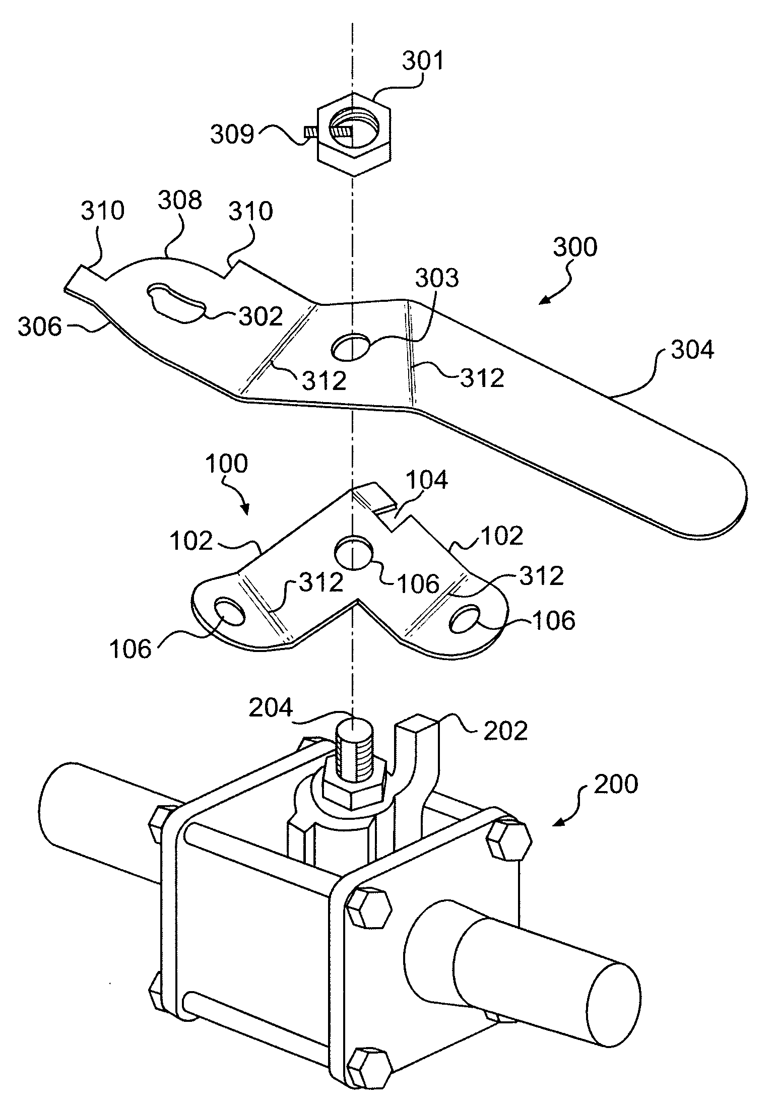
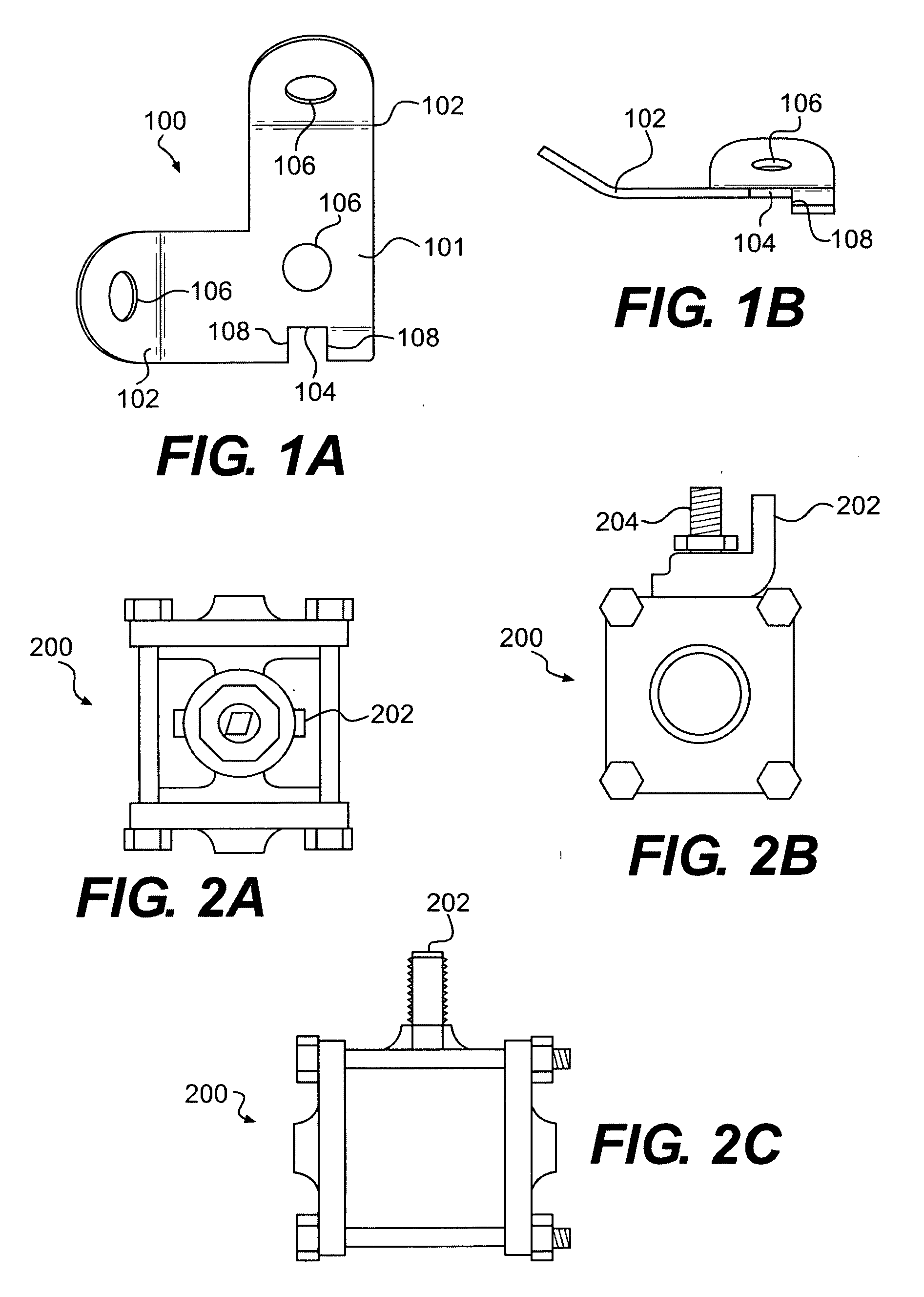
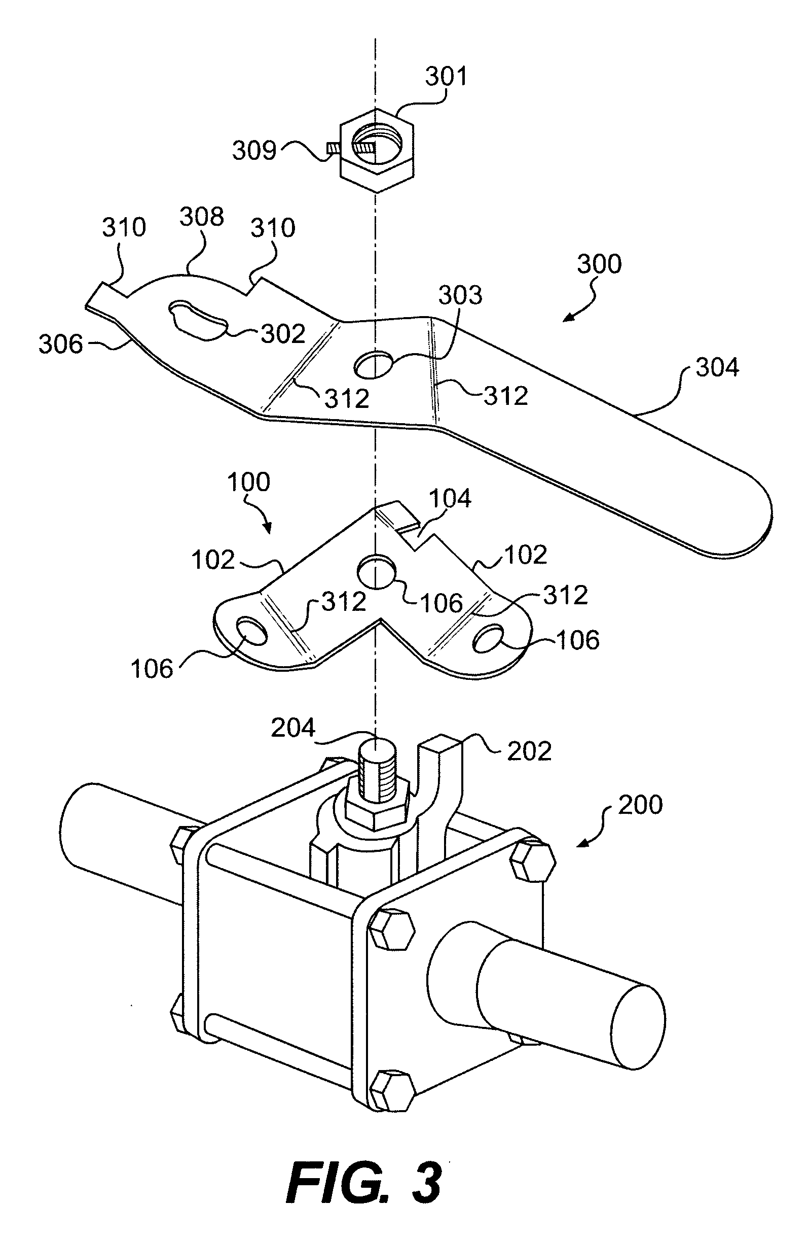
[0015]Reference will now be made in detail to a first embodiment of the present invention, an example of which is illustrated in the accompanying drawings. With reference to FIGS. 1A and 1B, a top and side view respectively of an exemplary embodiment of a valve locking device 100 are shown. The valve locking device 100 may be fitted between a valve and a valve handle for the valve as shown in FIG. 3.

[0016]The valve locking device 100 may include a rigid body having a central portion 101, two arms 102 extending outward from the central portion and a notch 104 in the central portion. The valve locking device 100 may be any kind of rigid body, such as an L-shaped bracket and may have various shapes, sizes and orientations. The arms 102 may extend outward in directions towards the open and closed positions. The notch 104 may be shaped to mate with an integrated stopper on the valve to lock the valve with the valve handle in either the open or the closed position. The valve locking devic...


PUM


Abstract

A device for locking a valve having an integrated stopper on the valve body and a valve handle with a locking hole in either an open or a closed position is disclosed. The valve handle is adapted to pivot a central valve post to rotate the valve between the open and closed positions. The device may include a rigid body having a central portion, and first and second arms extending outward from the central portion. Two holes may be provided in the arms to register with the locking hole in the valve handle and a third hole in the central portion of the rigid body may receive the central valve post. A notch sized to securely receive the integrated stopper may be provided in the central portion of the rigid body.

Description

FIELD OF THE INVENTION[0001]The present invention relates to a device for locking or anti-tampering, and particularly a device for locking a valve with a handle in either an open or a closed position.BACKGROUND OF THE INVENTION[0002]In some fluid flow systems, the operating position of a particular regulating valve may be critical to the proper functioning of the system. The improper operation or positioning of such a valve may result in a complete malfunction of the system, often with serious and dangerous consequences. For this reason, it is often desirable to securely lock the fluid-flow valve at one or more operating positions to prevent tampering and unauthorized or inadvertent operation of the valve. For example, one kind of fluid flow valve is a medical gas ball valve, which resides on the top of a canister of a tank of gas for use in medical environments and in all medical gas building piping systems upstream and downstream from zone valves, as indicated in the medical gas c...

Claims


Application Information

Patent Timeline
IPC IPC(8): F16K35/02
CPCF16K35/10F16K35/06
Inventor LEBLANC, RONALDBABINEAU, ALFRED
Owner JRA LOCK
Why Eureka
Eureka Blog
Learn More