
Slide with positionable chair and a repositioning attachment

Inactive Publication Date: 2009-06-18
GASSER CHAIR
View PDF8 Cites 2 Cited by
  • Summary
  • Abstract
  • Description
  • Claims
  • Application Information

AI Technical Summary

Benefits of technology

[0007]It is thus an objective of the present invention to allow for the attachment of an object, for example a casino chair, to the floor, or other such secure structure, while still allowing a specific amount of movement to provide a level of added comfort and utility to the object. As such, the present invention would satisfy the fire safety laws of numerous states, while still allowing for some limited movement of the object.
[0008]In the example of the casino chair or stool, the chair, in many states, must be securely attached to the floor or to a stationary object such as a gaming machine. However, it is also in the casino's interest that the chair be as comfortable as possible. Thus, the present invention satisfies both of these characteristics in that the chair is securely attached to the gaming machine while also allowing for a limited amount of movement. This movement, in one embodiment, allows the chair to slide to and away from the gaming machine, with a default, or start, position at a point, typically, closest to the gaming machine. On the other hand, the default position may also be at a point farthest from the gaming machine. A user may then adjust the chair to and away from the gaming machine to increase the user's level of comfort.

Problems solved by technology

These laws severely hinder the possibility of having chairs in the casino that are comfortable and easily maneuverable since it is required that they be secured in place.
As a result, chairs in casinos which must abide by these laws are usually less comfortable and less maneuverable, which may adversely affect the business of the casino.
In this type of situation, the chairs may be moved in any direction and may thus cause the casino floor to appear cluttered and disorganized.

Method used


Image

  • Slide with positionable chair and a repositioning attachment
  • Slide with positionable chair and a repositioning attachment
  • Slide with positionable chair and a repositioning attachment

Examples


Embodiment Construction

[0028]The present invention will be described and shown with respect to gaming chairs for gaming machines in casinos to which it is particularly adapted for use. However, those skilled in the art will recognize that this is only by way of illustration and not intended to so limit the invention. It will be understood that the present invention is applicable to the moving of all sorts, shapes and sizes of objects where the preferred movement is along a single line of directional movement for any given application or purpose.

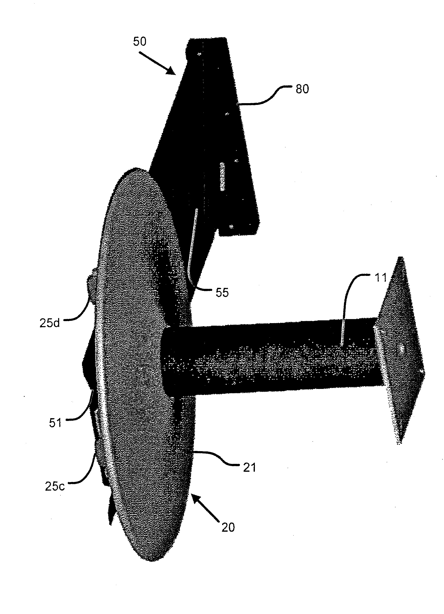
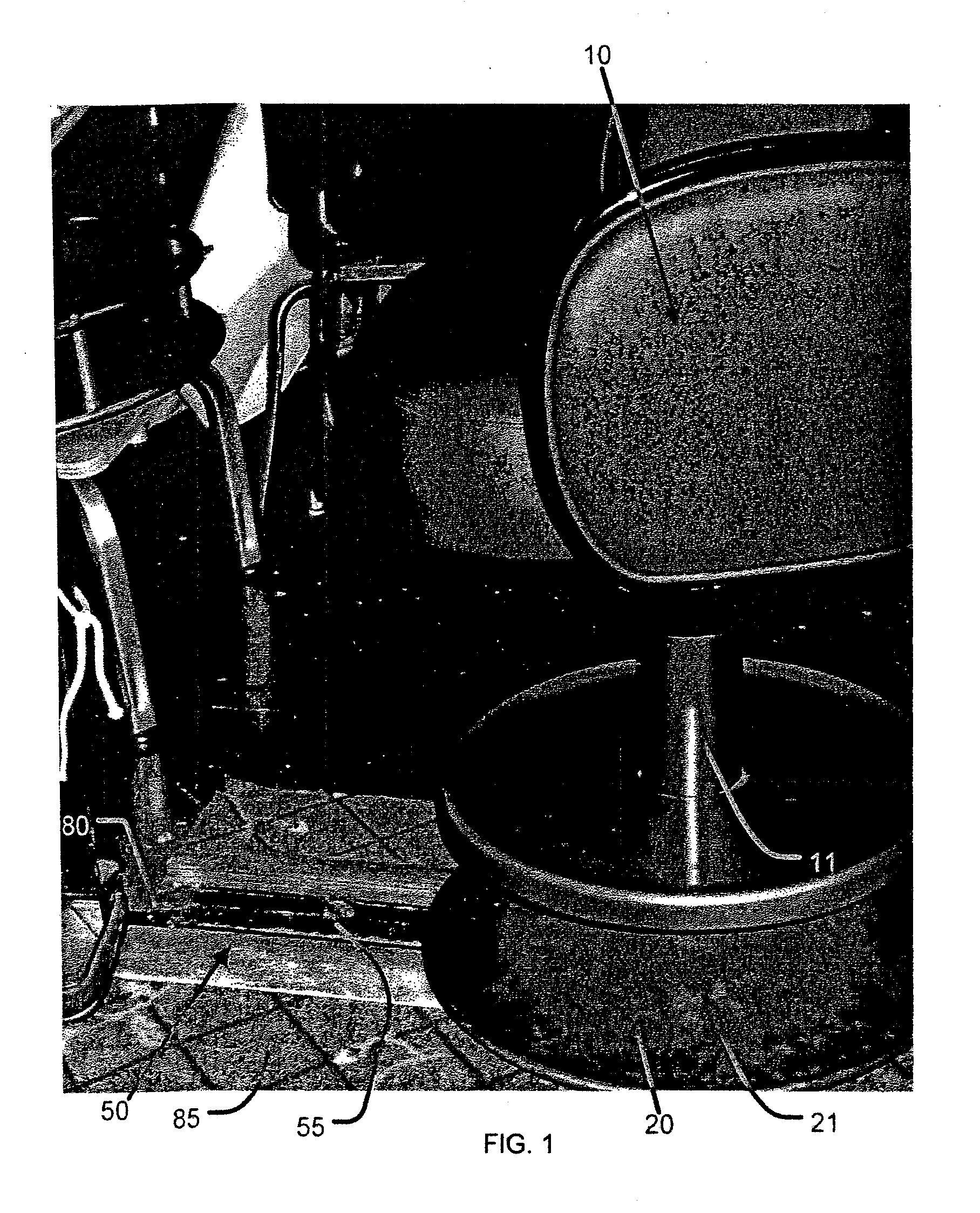
[0029]Thus, referring to the drawings, FIG. 1 shows one embodiment of a freely movable casino gaming chair generally designated 10 which is adapted for use with an associated gaming machine, not shown. The gaming chair illustrated is one type of ergonomic seating to which the present invention is particularly applicable because it enables the user to easily move such comfortable seating and adapts the gaming chair for movement in and along a single directional line...


PUM


Abstract

One embodiment of the present invention may include a support assembly adapted to be connected to an object for moving the object along a track, including a sled base having a track defined along at least a portion of its length, and an attachment support for supporting an object having an upper region and a lower region, the upper region may be adapted to be coupled to the object, and wherein the lower region of the attachment support may be moveably coupled to the track such that the attachment support may be slidable along at least a portion of the length of said track. The support assembly may be adjusted by a user to adjust the distance between the object and a solid object either in front of or behind the object. Additionally, the support assembly may also include an automatic repositioning mechanism which may automatically return the object to its original position once the user vacates the object.

Description

CROSS REFERENCE TO RELATED APPLICATIONS[0001]This application claims the benefit of the filing date of U.S. Provisional Patent Application No. 61 / 002,485, filed Nov. 9, 2007, the disclosure of which is hereby incorporated by reference herein as if fully set forth herein.BACKGROUND OF THE INVENTION[0002]This invention relates generally to means for moving objects such as a rolling base support for generally larger objects such as, for example, the popular ergonomic type gaming chairs now in use with associated gaming machines in gaming casinos.[0003]In recreation and other facilities and activities such as fishing boats and casinos, the movement of objects and chairs and providing means to make them more comfortable and easier to move, operate or use has received much attention.[0004]In casinos it has become popular to use chairs with the gaming machines to make it more comfortable for patrons so they will not leave due to discomfort. For example, in U.S. Pat. No. 5,522,641 an Adjust...

Claims


Application Information

Patent Timeline
IPC IPC(8): A47C1/00A47B96/06
CPCA47C15/004
Inventor GASSER, MARK E.
Owner GASSER CHAIR
Features
  • Generate Ideas
  • Intellectual Property
  • Life Sciences
  • Materials
  • Tech Scout
  • Unparalleled Data Quality
  • Higher Quality Content
  • 60% Fewer Hallucinations
Learn More