Plasma display device and plasma display panel drive method

a technology of plasma display panel and drive method, which is applied in the direction of electric digital data processing, instruments, computing, etc., can solve the problems of inability to make stable discharges, difficult to generate discharges, and inability to obtain stable discharges, so as to prevent an error display

Inactive Publication Date: 2009-06-18
MAXELL HLDG LTD
View PDF7 Cites 7 Cited by
  • Summary
  • Abstract
  • Description
  • Claims
  • Application Information

AI Technical Summary

Benefits of technology

[0012]The present invention has been made regarding the problems such as those mentioned in the foregoing, and an object thereof is to provide a technique capable of preventing an error display arising from, especially, changes in discharge property in a reset period due to a long-period operation of a PDP device.
[0014]In the PDP device of the present invention, according to operation time and conditions (states), a slope waveform of a reset period is changed and a waveform which makes discharges stable is maintained. More specifically, a slope waveform in a reset period which is required or desired to adjust charges precisely is made to have a configuration of slopes adapted to characteristics (changes thereof) of a protective layer and so forth of the PDP, and the slope is changed to be gentler in accordance with the operation time. In this manner, preferred weak discharges (continuous weak discharges) described above are generated in an operation in a reset period, thereby achieving fine control and preventing error display.
[0020]The effects obtained by typical aspects of the present invention will be briefly described below. According to the present invention, in a technique for a PDP device, it is possible to prevent an error display arising from changes in discharge characteristics in a reset period due to a long-period operation of a PDP device.

Problems solved by technology

The conventional AC-type and color-display PDP device has had a problem that the voltage waveform (slope waveform) having slopes like the reset waveform described above cannot make stable discharges as characteristics of discharge generally changes when performing operations of a PDP device (including PDP) for a long time.
Generally, the protective layer (MgO) mentioned above has less electron emissions, especially, as a long period of time passes in an operation period of a PDP device (PDP), so that discharges become difficult to be generated.
Accordingly, in the case where the operation time of the PDP device is particularly long, performing the continuous weak discharges which is fine control is difficult to make, so that stable discharges cannot be obtained.
While the reset period has the function described above, it is feared that, in the case where the strong discharges mentioned above are generated in a reset period at a non-selected cell (non-target On cell) due to the problems described above, charges are generated in the cell and discharges are generated in a sustain period even when no select pulse is applied in an address period, that is, it leads to an error display.

Method used


Image

  • Plasma display device and plasma display panel drive method
  • Plasma display device and plasma display panel drive method
  • Plasma display device and plasma display panel drive method

Examples


first embodiment

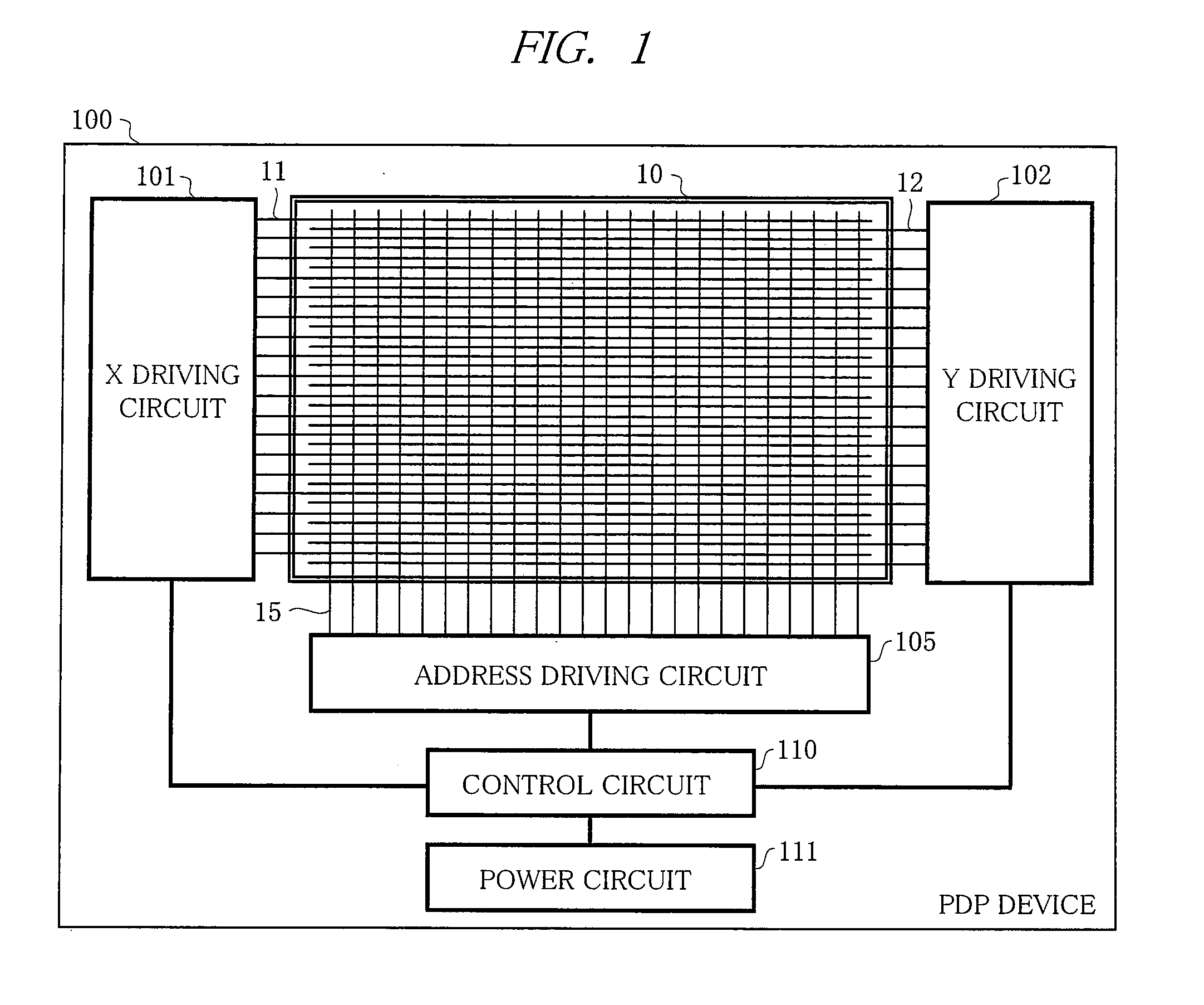
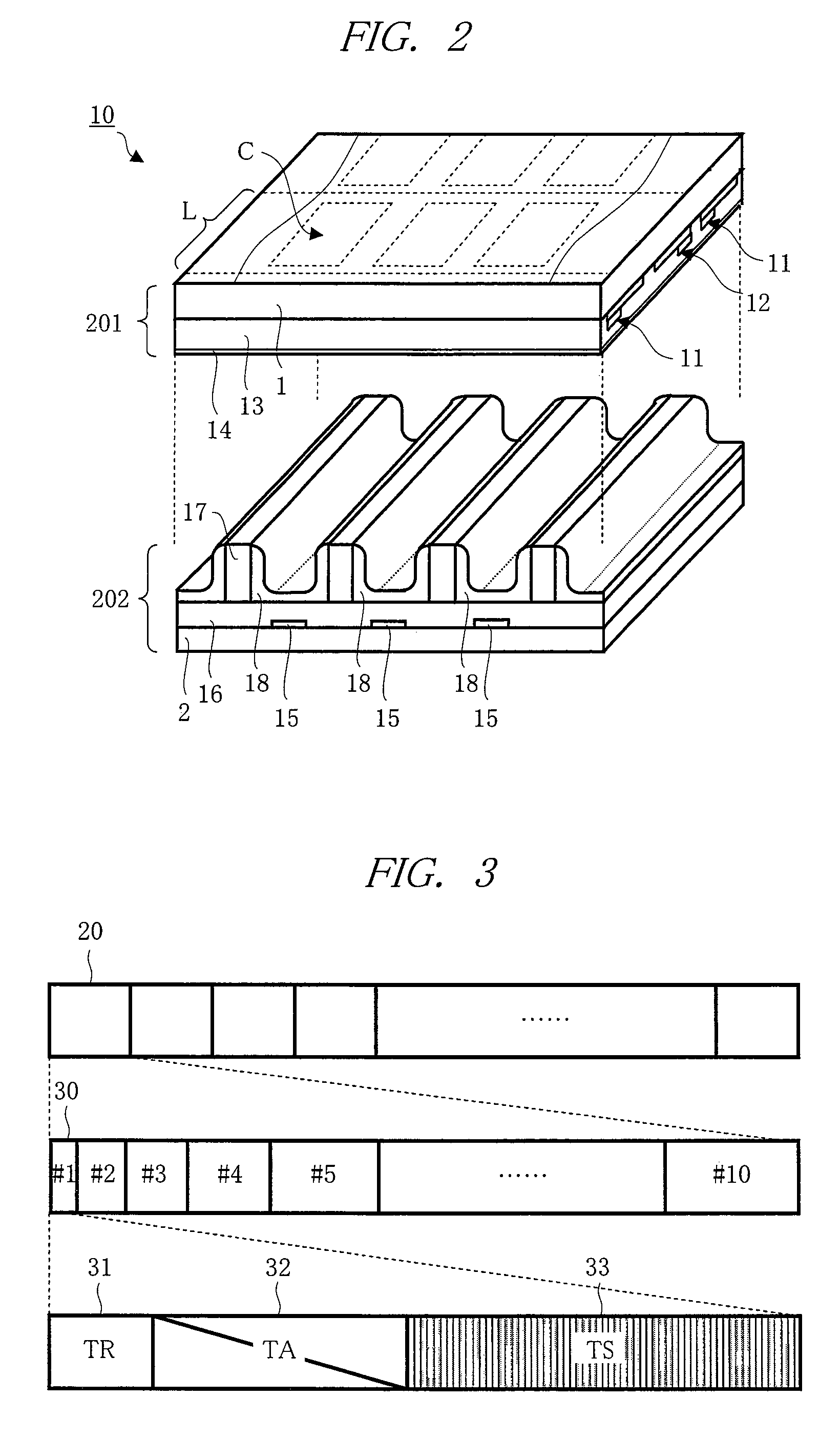
[0037]With reference to FIG. 1 to FIG. 12, a first embodiment of the present invention will be described. A feature of the first embodiment is, being particularly shown in FIG. 5 and FIG. 6, to change rising and falling slope waveforms of a reset waveform to a scan electrode of a PDP according to operation time of a PDP device (denoted as T), and respective waveforms after the change are composed by slope waveforms having different two-step slopes. To comprehend the operation time (T), an accumulated counter value of a number of sustain pulses is used.

[0038]

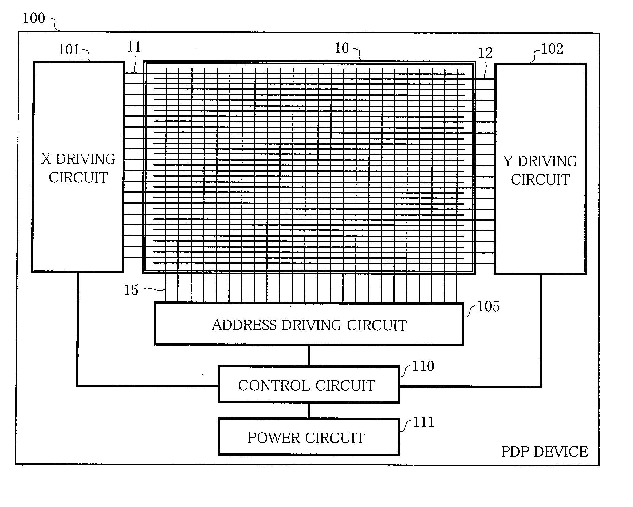
[0039]First, in FIG. 1, an overall configuration of a PDP device (PDP module) 100 of the present embodiment will be described. The present PDP device 100 has, mainly, a configuration having an AC-type PDP 10 and a circuit part for driving and controlling the PDP 10. The PDP module is held to a chassis part not shown having the PDP 10 attached thereto, in which the circuit part is configured by an IC etc., and the PDP 10 and the c...

second embodiment

[0109]Next, with reference to FIG. 13, a second embodiment of the present invention will be described. The second embodiment has same basic configuration as that of the first embodiment, and has different method and configuration for monitoring operation conditions and operation time (T) for changing (switching) slopes of a slope waveform in TR 31. In the second embodiment, as an operation condition to use in control for driving, comprehension of sustain power (total power consumption) is used in the control circuit 110, so that the slope waveform in TR 13 is controlled to drive in accordance with the periods (t0 to t2) similar to the first embodiment.

[0110]2)>

[0111]In FIG. 13, a configuration of the control circuit 110 according to the second invention will be described. The control circuit 110 has a different part from the first embodiment that a sustain power cumulative counting circuit 75 is provided, so that a sustain power cumulative value (estimated from the start of using th...

third embodiment

[0114]Next, with reference to FIG. 14, a third embodiment of the present invention will be described. In the third embodiment, as compared with the first embodiment, the basic configuration is same, and a method and configuration of monitoring operation conditions and operation time (T) for changing (switching) the slope of a slope waveform in TR 31 are different. In the third embodiment, as an operation condition used in drive control, comprehension of conducting time (energizing time) is used so that a slope waveform in TR 13 is controlled for driving corresponding to the periods (t0 to t2) similarly to the first embodiment.

[0115]3)>

[0116]In FIG. 14, a configuration of the control circuit 110 according to the third embodiment will be described. The control circuit 110 has, as a different part from the first embodiment, a conducting time cumulative counting circuit 78 is provided, and total conducting time (approximately calculated from the start of using PDP 100) is comprehended, ...


PUM


Abstract

Provided is a technique of a PDP device capable of preventing error display arising from changes in discharge characteristics in a reset period particularly due to a long-period operation. In the PDP device, a slope of a slope waveform in the reset period is changed corresponding to operation time of the PDP device. And, the slope waveform is made to have a configuration having a stepwise plurality of slopes in a predetermined reset period. For example, when the operation time becomes long, rising and falling slope waveforms of a reset waveform are configured by two steps, and a first slope thereof is made steeper than a slope before the change, and a second slope is made gentle than the slope before the change. When the operation become longer, the first slope is made further steeper and the subsequent second slope is made further gentler.

Description

TECHNICAL FIELD[0001]The present invention relates to a technique for a method of driving a plasma display panel (PDP) and a display device thereof (plasma display device: PDP device), and more particularly, the present invention relates to an operation in a reset period for drive control of subfields.BACKGROUND ART[0002]Currently, PDP device is in practical use as a flat display being high-luminance, thin, and capable of large-screen display, and its overall operation properties have been improved along with improving display quality. PDP is a display device which performs display using discharges, and generally configured by several hundreds of thousands to several millions of pixels. Generally, in display of an AC-type PDP device, each field that becomes a screen is configured by a plurality of subfields having different luminance weightings. Each subfield is configured by, for example, a reset period, an address period, and a sustain period.[0003]Reset period is a period for gen...

Claims


Application Information

Patent Timeline
Patent Type & Authority Applications(United States)
IPC IPC(8): G06F3/038G09G3/28G09G3/20G09G3/291G09G3/292G09G3/298
CPCG09G3/292G09G3/2922G09G2310/066G09G3/2944G09G2300/0426G09G3/2927
Inventor KAMINAKA, TETSUYASHIZAKI, TAKASHISASAKI, TAKASHIKURIYAMA, HIROHITO
Owner MAXELL HLDG LTD
Why Eureka
Try Eureka