
System and method for detecting optical defects

a technology of optical defects and optical components, applied in the field of inspection systems, can solve the problems of difficult to correlate the response of the patient to the drug with the dosage given, the dose may be so severe, and the difficulty in achieving the effect of detecting the optical d

Inactive Publication Date: 2009-06-18
TENSOR ID
View PDF4 Cites 41 Cited by
  • Summary
  • Abstract
  • Description
  • Claims
  • Application Information

AI Technical Summary

Benefits of technology

[0009]The various aspects of the systems and methods of the present invention provide for non-destructive inspection of the transparent or semi-transparent articles or structures to identify the presence or absence of defects or additives on a selected surface of the article or structure, and if present, provide for analyzing an image of

Problems solved by technology

This is problematic because it will be difficult to correlate the response of the patient to the drug with the dosage given.
In some cases, the under dose may be so severe as to provide little or no medication to the patient.
While such under medication may be observed and corrected by the care giver providing the injection, it is inconvenient and requires giving partial dosages from another syringe, which may be difficult to accomplish, and is also costly because it results in wasted drug.
Where the drug is administered by the patient, incomplete injection may not even be noticed by the patient.
However, due to locating problems, nozzle inconsistencies, or inconsistency in the pressure used to spray the silicone oil into the syringe, the distribution of the silicone oil within the barrel may vary along the length and / or circumference of the barrel.
Additionally, this inconsistency can be exacerbated during storage of the pre-filled syringe, since the hydrophobic silicone oil tends to bead up when placed in contact with an aqueous solution.
Unfortunately, the current methods of assessing silicone oil distribution cannot be directly correlated to injection performance.
Additionally, such methods are typically destructive in nature, time consuming, and / or expensive.

Method used


Image

  • System and method for detecting optical defects
  • System and method for detecting optical defects
  • System and method for detecting optical defects

Examples


Embodiment Construction

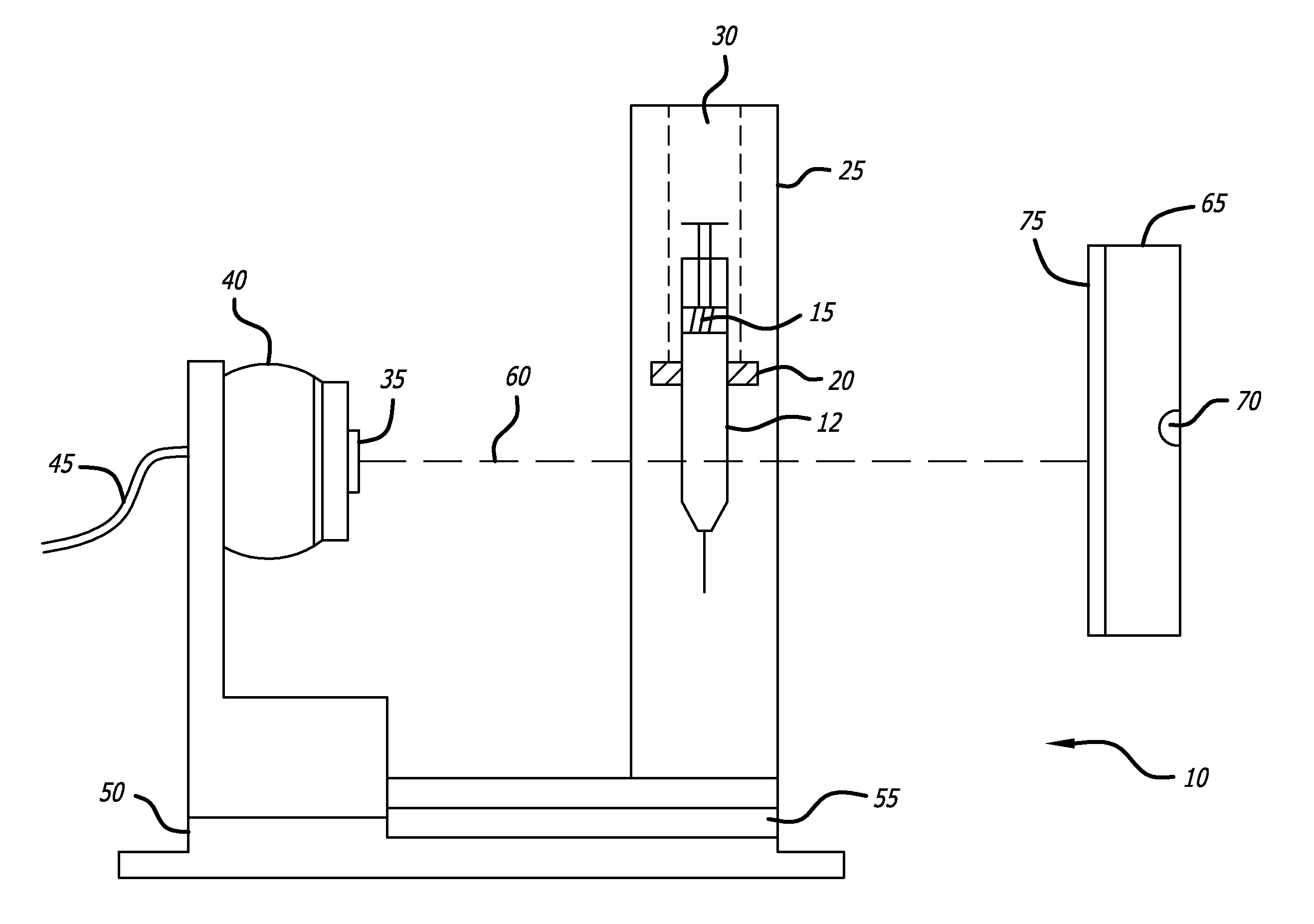
[0028]Referring now to the drawings in detail, in which like reference numerals indicate like or corresponding elements among the several figures, there is shown in FIG. 1 a front view of one embodiment of an inspection system 10 in accordance with principles of the present invention.

[0029]Inspection system 10 is an optical inspection system, and thus the components of the system to be described in more detail below will be understood to be mounted in such a way as to provide adjustment and movement of the various components so that an appropriate optical focus for the light passing through the components can be obtained. In this embodiment, a pre-filled syringe 12 having a plunger 15 is moveably mounted via a rotatable collar 20 to a mounting plate 25. Collar 20 is mounted to plate 25 via translating means 30 so that collar 20 can be translated upwards and downwards along the length of plate 25. Those skilled in the art will understand that this translation can be accomplished in a...


PUM


Abstract

A system and method for detecting optical defects on a surface of a transparent or semi-transparent structure, tube or article is provided. Defects are identified and analyzed by using a digital camera to capture an image of a target having a pattern of light and dark areas through a portion of the article. The images are processed to enhance the visibility of the defects, and the distribution of the defects as function of their location on the surface of the article is determined. This determination is used as part of a statistical process control method for controlling the level of defects present on the surface of the article.

Description

CROSS-REFERENCES TO RELATED APPLICATIONS[0001]This application claims priority from U.S. Provisional Application No. 61 / 014,337, filed Dec. 17, 2007, incorporated by reference in its entirety.BACKGROUND[0002]This invention relates to inspection systems for characterizing the distribution of lubricating fluids applied to tubular barrels, and more particularly, to determining the consistency of distribution of lubricating fluid within a syringe for predicting the probability that incomplete ejection of the contents of the syringe will occur upon injection due to stalling of the plunger of the injector during injection.[0003]Use of pre-filled syringes in combination with auto-injectors is rapidly becoming a standard method of drug delivery. In such a system, a syringe is pre-filled with a drug to be delivered, and then may be stored for a period of time before use. The pre-filled syringe is then placed in an auto-injector, which, when activated, applies force to the plunger of the syri...

Claims


Application Information

Patent Timeline
IPC IPC(8): G06K9/00
CPCG01N21/958G01N21/90
Inventor WOLFE, GREGORY ADAM
Owner TENSOR ID
Learn More