Method of making aerosol valve mounting cups and resultant cups

a technology of aerosol valves and mounting cups, which is applied in the direction of liquid dispensing, hollow objects, domestic applications, etc., can solve the problems of non-circular blanks and less desirable, and achieve the effect of minimizing earring height and carefully controlling skirt heigh

Inactive Publication Date: 2009-06-25
PRECISION VALVE CORP
View PDF99 Cites 0 Cited by
  • Summary
  • Abstract
  • Description
  • Claims
  • Application Information

AI Technical Summary

Benefits of technology

[0008]The present invention produces mounting cups that do not require the aforesaid final trimming operation, and yet obtains a carefully controlled skirt height, preferably with a substantially even outer edge with minimized earring.

Problems solved by technology

Non-circular blanks can be used in the present invention, but are less desirable because of reasons including the need for more complicated pressing / drawing equipment that requires die alignments and equipment maintenance beyond that where circular blanks are used, and because of potentially excess material cost from the non-circular blank shape.

Method used


Image

  • Method of making aerosol valve mounting cups and resultant cups
  • Method of making aerosol valve mounting cups and resultant cups
  • Method of making aerosol valve mounting cups and resultant cups

Examples


Embodiment Construction

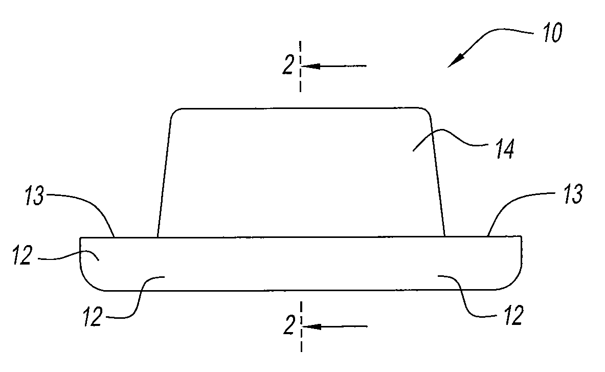
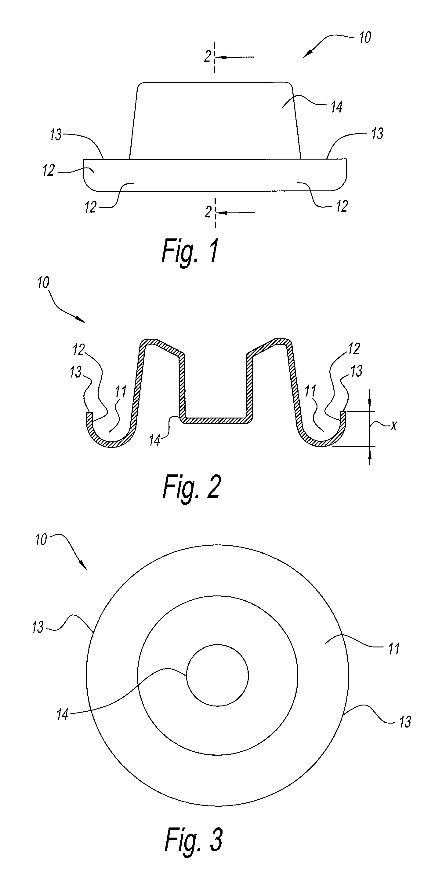
[0032]Referring to FIGS. 1, 2 and 3, a conventional aerosol mounting cup 10 is shown having a circular channel 11, a skirt 12 having a skirt height x, a skirt edge / lip 13, and a pedestal portion 14. The channel 11 is mounted over the well-known aerosol can bead (not shown) defining the can top opening, and the well-known aerosol valve (not shown) is mounted through the pedestal 14 of the aerosol mounting cup. All of this structure and assembly is well known in the aerosol art and needs no further description here.

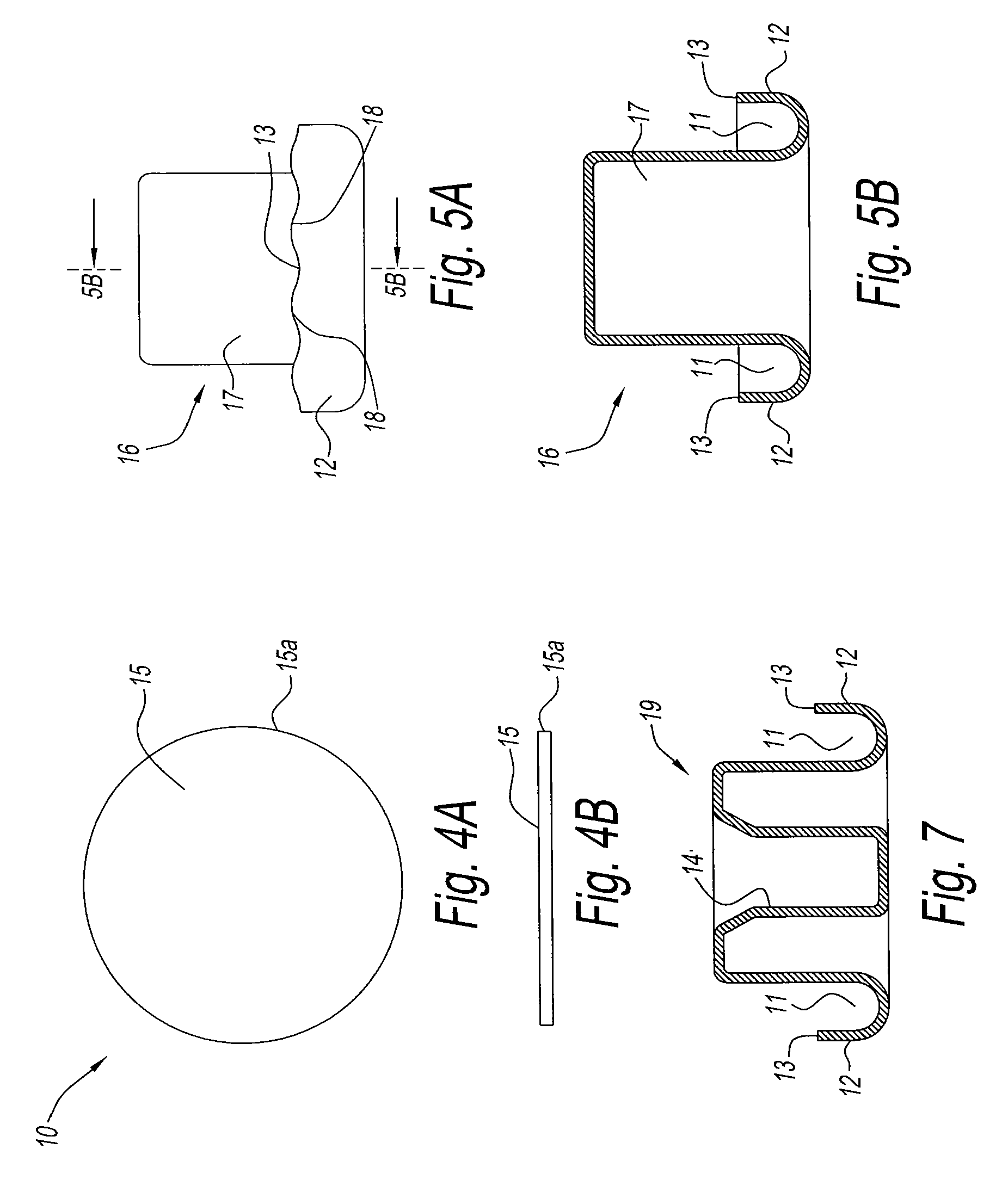
[0033]The aerosol mounting cup 10 of the present invention is made beginning with preferably circular metal disc 15 cut from a metal sheet and having cut edge 15a, as shown in FIGS. 4A and 4B. Circular metal disc will have a predetermined cut diameter, for example, 48.3 mm, that allows the benefits of the present invention to be obtained and without a conventional trimming operation. Metal disc 15 is then formed into a cupped preform 16 by a standard drawing operation in a ...


PUM

PropertyMeasurementUnit
diameteraaaaaaaaaa
angleaaaaaaaaaa
angleaaaaaaaaaa

Abstract

Metal discs, preferably circular, are cut to a precise diameter and drawn to a preform with a channel and skirt for an aerosol valve mounting cup. The preform then undergoes further forming operations at the stations in a press system. “Bumping” is carried out on the skirt edge at a station, to eliminate non-burr trimming of the cup edge, save material and obtain a carefully controlled skirt height and a substantially even skirt edge with minimized earring. The resultant cup terminating skirt edge is characterized by reformed metal. A further coaxing or pinch-cut operation may be performed on the cup skirt.

Description

RELATED APPLICATION [0001]This application is a continuation-in-part of U.S. application Ser. No. 11 / 820184, filed Jun. 18, 2007.FIELD OF THE INVENTION [0002]The present invention relates to aerosol valve mounting cups into which are mounted aerosol valves and which cups are in turn mounted onto the tops of aerosol product containers. More particularly the present invention relates to a new method of manufacturing said mounting cups, and the resultant cups.BACKGROUND OF THE INVENTION [0003]The well known and long existing aerosol valve mounting cup is generally a metal member having an outer circular channel that is placed over the circular bead of the aerosol can defining the opening into the aerosol can. The outer side of the channel terminating in a circular edge is commonly known as the skirt of the mounting cup and is crimped onto the can bead with a sealing medium (sleeve gasket, laminated gasket, cut gasket, coated gasket, etc.) positioned in between the channel and can bead....

Claims


Application Information

Patent Timeline
Patent Type & Authority Applications(United States)
IPC IPC(8): B23P17/00
CPCB21D51/38Y10T29/49B65D83/38
Inventor DUFFIELD, DEAN W.
Owner PRECISION VALVE CORP
Why Eureka
Try Eureka