Device for connecting two pipes with different external diameters

a technology of external diameter and pipe, which is applied in the direction of pipe connection arrangement, pipe/joint/fitting, sleeves/socket joints, etc., can solve the problems of unfavorable spatial deformation process, adverse effect of connection seal, and inability to achieve a targeted spatial deformation process, etc., to achieve low cost production, easy sealing, and high quantity

Active Publication Date: 2009-06-25
FELBER WINFRIED
View PDF16 Cites 26 Cited by
  • Summary
  • Abstract
  • Description
  • Claims
  • Application Information

AI Technical Summary

Benefits of technology

[0012]Another preferred version of the main measures may be that at least the slots which extend over the central section of the fixing sleeve are bridged by a bellows-type membrane and that to each contact section a seal is assigned projecting out of the central section coming to rest on the appropriate pipe. The membranes close the relevant expansion slots without having an adverse effect on the movement produced by the expansion and compression slots. The central section of the fixing sleeve which bridges the butt joint area between the two pipes can be sealed easily by the seals assigned to the contact sections and which come into contact with the pipes. This means that there is no need for a sealing sleeve. Nevertheless a well sealed arrangement can be achieved. In accordance with the first version only the internal slots can be bridged by a bellows-type membrane wherein a meandering sealing cord may be fitted between the internal slots bridged by a membrane and the open edge notches. Another version may be that all the expansion slots formed by the edge notices and internal slots are bridged by a bellows-type membrane wherein a surrounding sealing ring is fitted in a channel in the area of the ends of the side contact sections away from the central section, and this is against the neighbouring face sides of the membranes open on the channel side.
[0013]In another development of the main measures, the spring cage which forms the fixing sleeve may consists of several ring segments which can be combined to form a ring wherein the central sections and the axial projections of neighbouring ring segmen

Problems solved by technology

However, this has proved to be both complicated and uneconomical since different compensating rings have had to be kept at the ready for different diameter differences.
The compensating rings are located in a radial position inside the sealing sleeve and can therefore also have an adverse effect on the seal of the connection.
Although the overlapping ends can move towards each other, it

Method used


Image

  • Device for connecting two pipes with different external diameters
  • Device for connecting two pipes with different external diameters
  • Device for connecting two pipes with different external diameters

Examples


Embodiment Construction

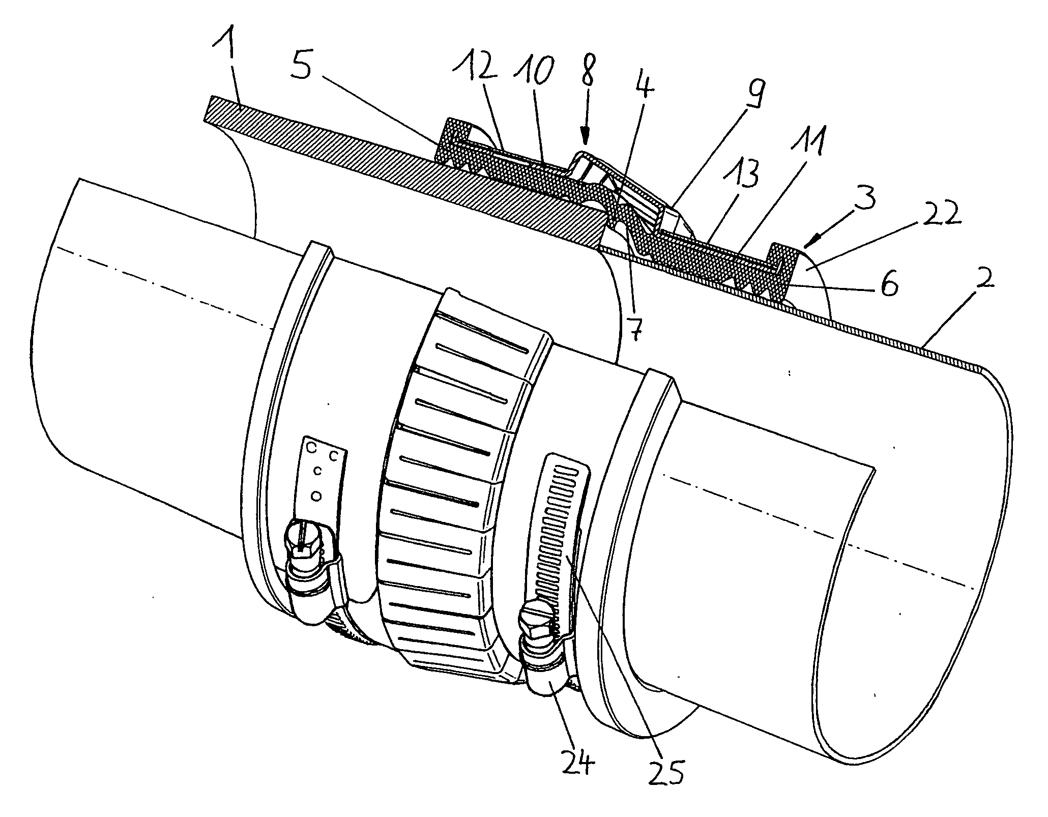
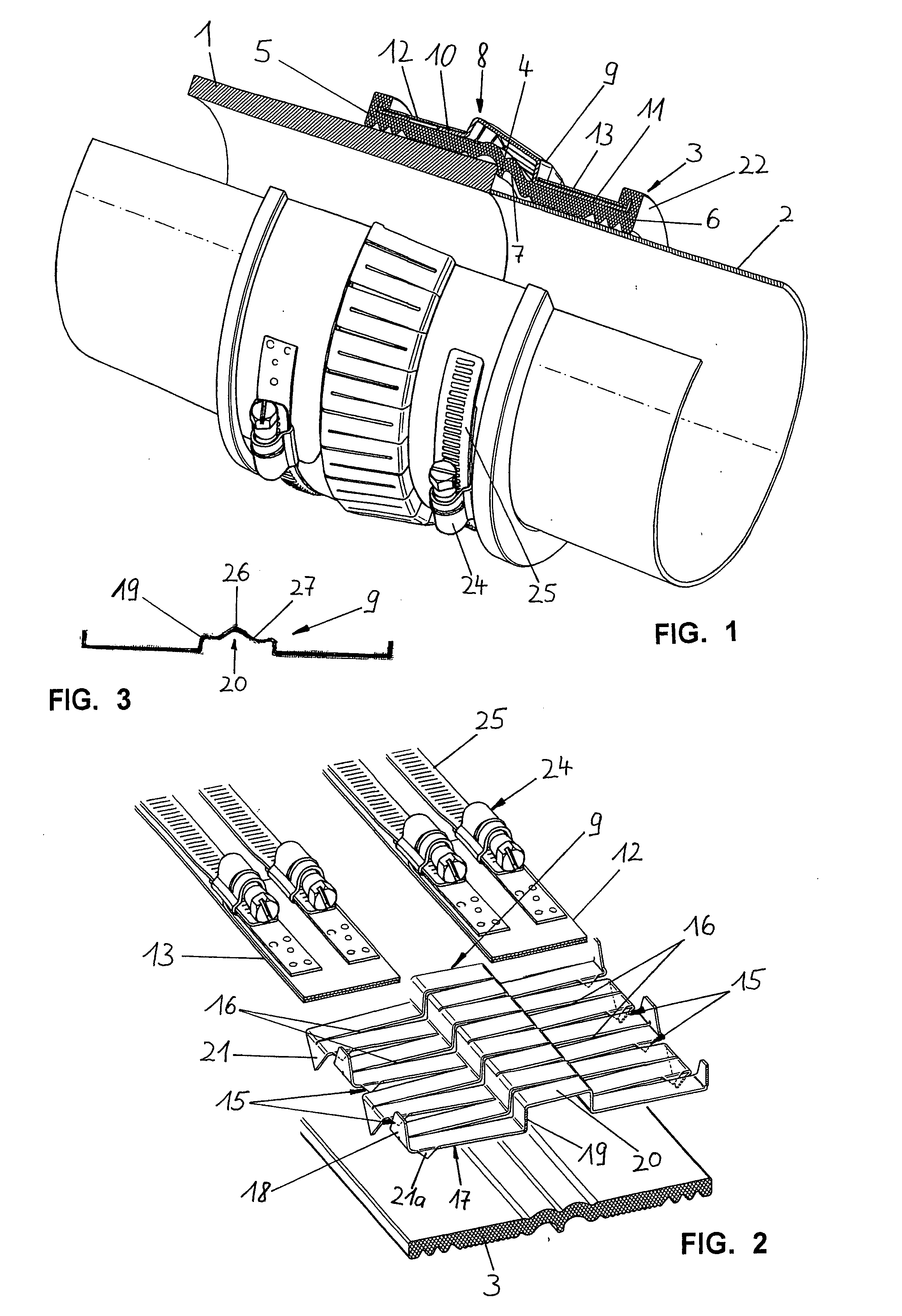
[0017]FIG. 1 A pipe connection as proposed by the invention with a fixing sleeve in the form of an encircling spring cage in a section view.

[0018]FIG. 2 A detailed view of the arrangement shown in FIG. 1 in an exploded view.

[0019]FIG. 3 A cross-section of a preferred version of the fixing sleeve.

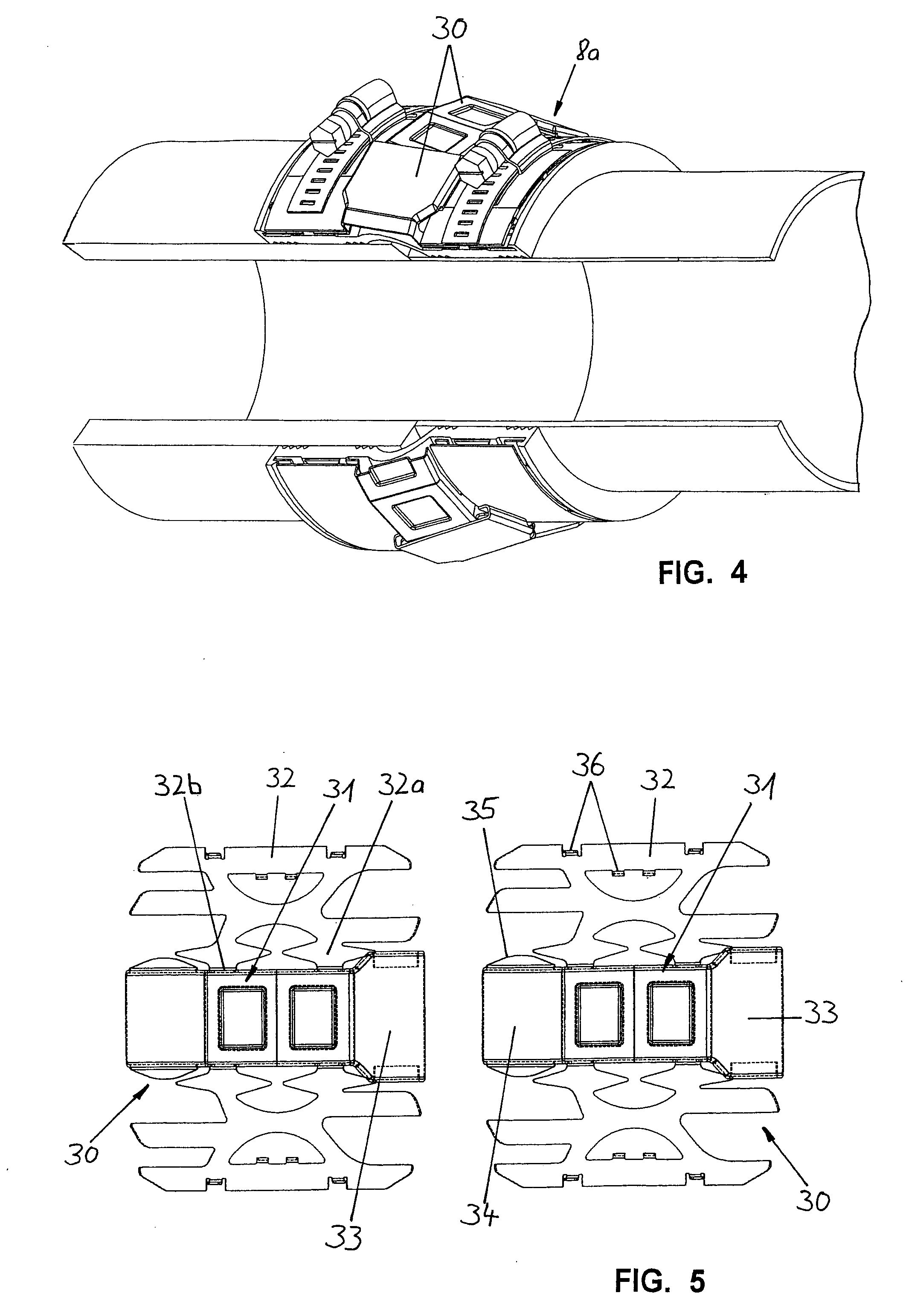
[0020]FIG. 4 A pipe connection as proposed by the invention with a fixing sleeve formed by inter-connected encircling segments in a section view.

[0021]FIG. 5 A plan view of two consecutive encircling segments of the arrangement in FIG. 4.

[0022]FIG. 6 A perspective view of a spring cage formed by inter-connected ring segments.

[0023]FIG. 7 A view of a single ring segment of the arrangement shown in FIG. 6.

[0024]FIG. 8 A schematic view of a version with expansion slots formed only by edge notches.

[0025]FIG. 9 A view of a multi-part clip.

[0026]FIG. 10 An alternative to the cross-section shown in FIG. 3.

[0027]FIG. 11 An alternative to the version shown in FIG. 7.

[0028]FIG. 12 An internal view of ...


PUM


Abstract

For a device for connecting two pipes (1, 2) with different external diameters using a sleeve arrangement which bridges the butt joint between the ends of the pipe (1, 2) facing each other and contains at least a fixing sleeve (8, 8a) which can take up the clips (12, 13) for the two pipes (1, 2) and if necessary a sealing sleeve (3) which is surrounded by the fixing sleeve (8, 8a), high economy and safety can be achieved by the fact that each sleeve of the sleeve arrangement has cylindrical contact sections (5, 6; 10, 11) which can be adjusted to the different external diameters of the two pipes (1, 2) and are connected by a central section (7, 9) which can take a conical form to suit the diameter difference wherein the contact sections (5, 6) of the sleeve next to the external circumference of the two pipes (1, 2) can be brought into direct contact with the two pipes (1, 2) and the contact sections (10, 11) of the fixing sleeve (8, 8a) contain encircling mounting channels assigned to the clips (12, 13) and wherein the fixing sleeve (8) takes the form of a closed encircling ring which is suitable for three-dimensional deformation.

Description

FIELD OF THE INVENTION[0001]The invention relates to a device for connecting two pipes with different external diameters with a sleeve arrangement which bridges the butt joint between the ends of the pipe facing each other and contains at least a fixing sleeve which can take up encircling clips assigned to the two pipes and if necessary a sealing sleeve which is surrounded by the fixing sleeve.BACKGROUND OF THE INVENTION[0002]The need to connect lines, in particular pipes with different external diameters, comes about if pipes are found with different wall thicknesses, for example made of different materials, a situation which often occurs in the waste water and sanitary field. In arrangements of the type mentioned above used in the past have used compensating rings which have compensated for the diameter difference between the two pipes. However, this has proved to be both complicated and uneconomical since different compensating rings have had to be kept at the ready for different...

Claims


Application Information

Patent Timeline
IPC IPC(8): F16L25/14
CPCF16L21/005F16L21/022F16L49/02F16L25/14F16L25/0072
Inventor FELBER, WINFRIED
Owner FELBER WINFRIED
Why Eureka
Try Eureka