

Automotive head up display apparatus
a display apparatus and head-up technology, applied in the direction of optics, static indicating devices, instruments, etc., can solve the problems of large optical loss, incongruity of image (virtual image) size, difficult visual recognition, etc., and achieve the effect of changing the display distan
- Summary
- Abstract
- Description
- Claims
- Application Information
AI Technical Summary
Benefits of technology
Problems solved by technology
Method used
Image

Examples
first embodiment
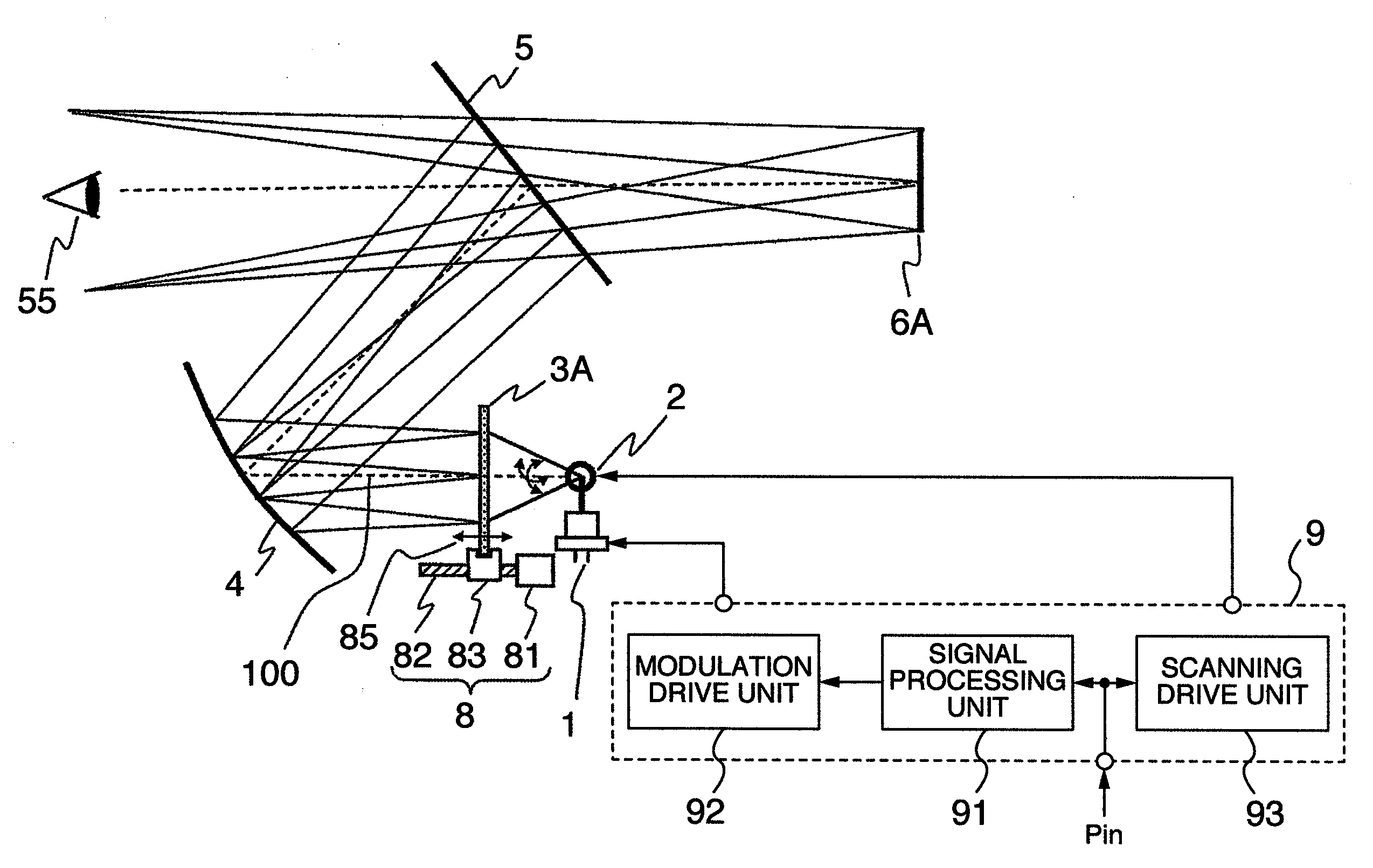
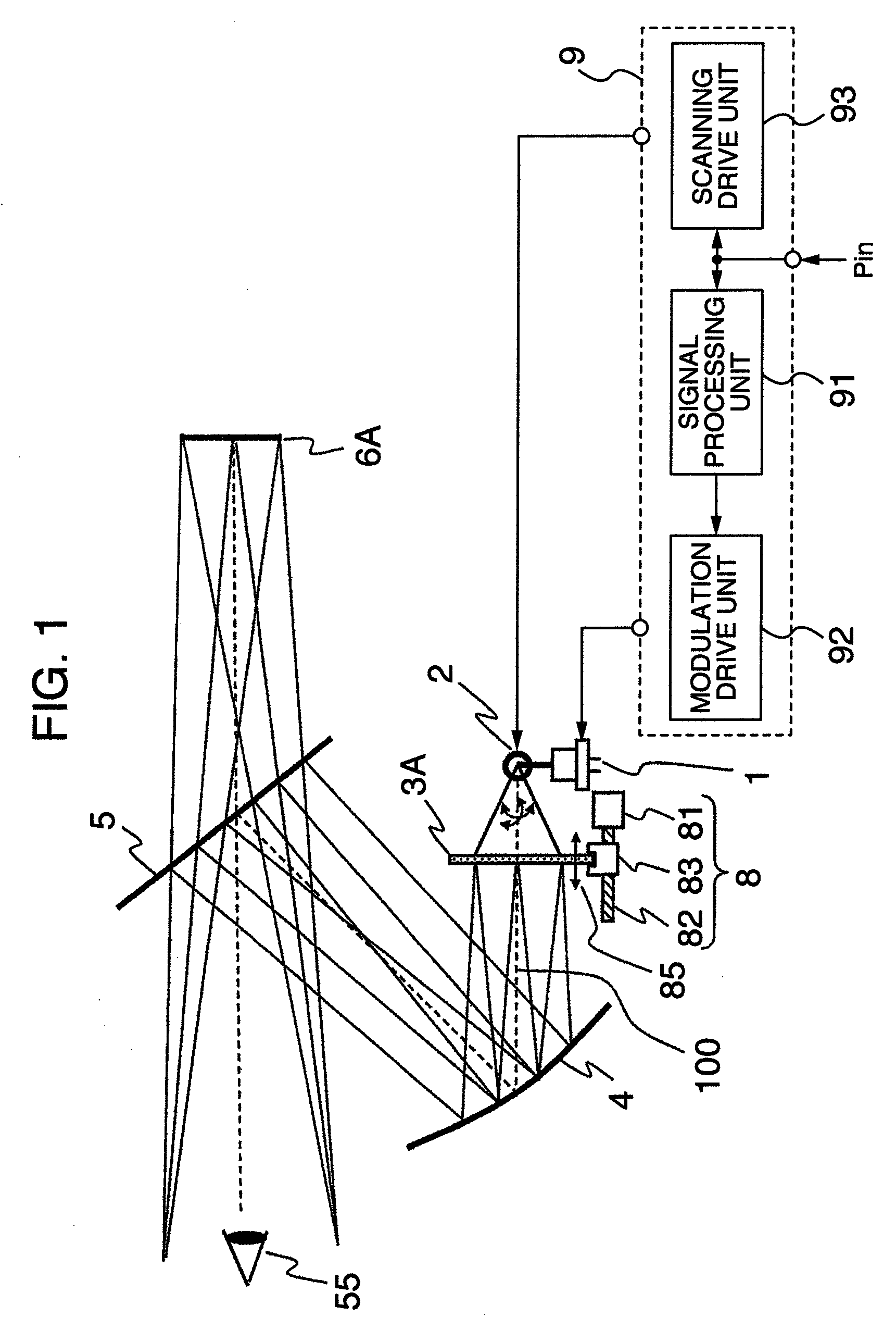
[0026]The HUD apparatus according to this embodiment for projecting a virtual image in a predetermined size regardless of the display distance thereof is explained below with reference to FIGS. 1 and 2.
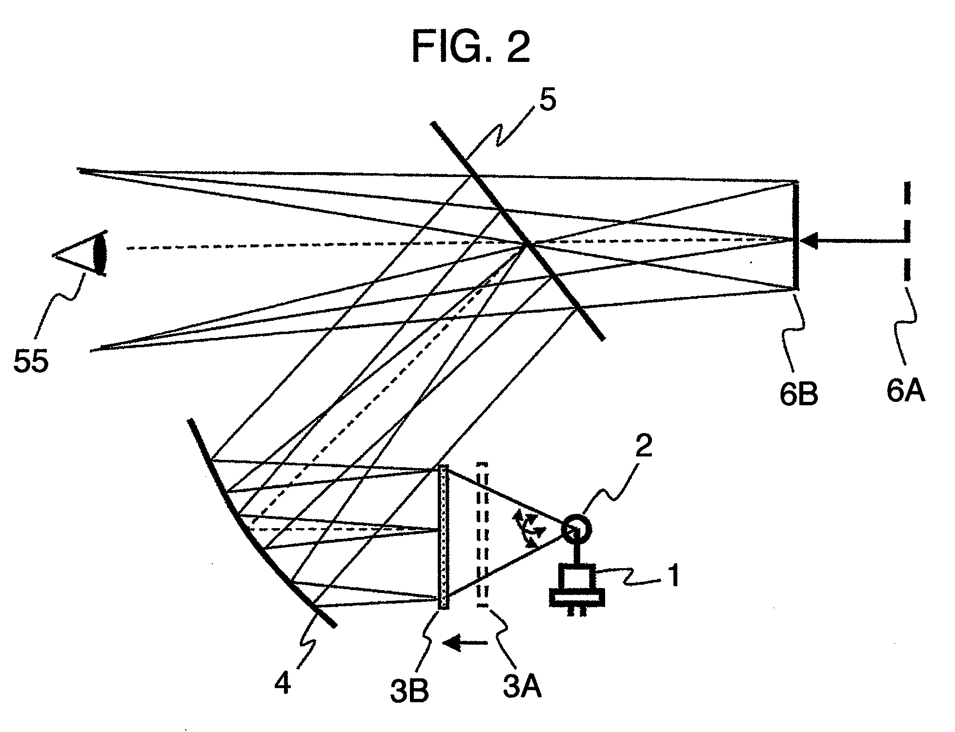
[0027]FIG. 1 is a side view schematically showing the HUD apparatus according to the first embodiment. FIG. 2 is a diagram for explaining the movement of the virtual image according to this embodiment. In FIGS. 1 and 2, the elements with the position thereof moved are each designated by a reference numeral with a capital letter attached as an affix. Specifically, an element before movement is designated with “A” attached, and an element after movement with “B” attached. In an apparent case, however, the capital letters “A” and “B” will not be attached. In FIG. 2, the moving unit 8 and the control unit 9 are not shown for the sake of simplicity.
[0028]First, the configuration of the HUD apparatus according to this embodiment will be explained.
[0029]In FIG. 1, the HUD apparatus according...
second embodiment
[0052]The HUD apparatus according to a second embodiment in which a plurality of travel information, for example, can be projected with high brightness using the technique of the first embodiment is explained below with reference to FIGS. 3 and 4.
[0053]FIG. 3 is a top plan view schematically showing the essential parts of the HUD apparatus having a plurality of screens according to the second embodiment. FIGS. 4A and 4B are schematic diagrams for explaining a situation in which the driver visually recognizes a virtual image of a plurality of travel information projected using the HUD apparatus according to the second embodiment. FIG. 4A is a diagram schematically showing the situation in which the driver visually recognizes a plurality of travel information superposed on a front scene in the forward visual field through the windshield, and FIG. 4B is a diagram for explaining the corresponding relationship between the display image and the virtual image of each display image formed o...
third embodiment
[0069]Next, a HUD apparatus for projecting a color display image according to the third embodiment will be explained. FIG. 5 is a side view schematically showing the essential parts of the optical system of the HUD apparatus according to the third embodiment.
[0070]As shown in FIG. 5, the HUD apparatus according to the third embodiment includes light sources 1R, 1G, 1B corresponding to the three primary colors of red (R), green (G) and blue (B), wavelength synthesis units 7a, 7b, a scanning unit 2, a screen 3 and a mirror 4. Though not shown, the HUD apparatus also of course includes a moving unit for moving the screen 3 and a control circuit for controlling the light sources 1R, 1G, 1B and the scanning unit 2.
[0071]The wavelength synthesis units 7a, 7b may be formed of, for example, a dichroic mirror, a dichroic prism or a diffraction element. The wavelength synthesis unit 7a according to this embodiment has such a characteristic that the red light wavelength region is transmitted w...
PUM
 Abstract
Description
Claims
Application Information