
System for multi-media image magnification

Inactive Publication Date: 2009-06-25
EITAC SOLUTIONS GRP
View PDF0 Cites 8 Cited by
  • Summary
  • Abstract
  • Description
  • Claims
  • Application Information

AI Technical Summary

Benefits of technology

[0013]In accordance with one aspect of the present invention there is provided a vision magnification system to provide a magnified image of an object for viewing by a user. The system includes a fixed work area, to support the object, a camera, to provide an image of at least a portion the object, a camera movement control system taking inputs from the user and thereby controlling the movement of the first camera, and a drive system, coupled to the camera, to move the camera in at least one direction.
[0014]In accordance with another aspect of the present invent

Problems solved by technology

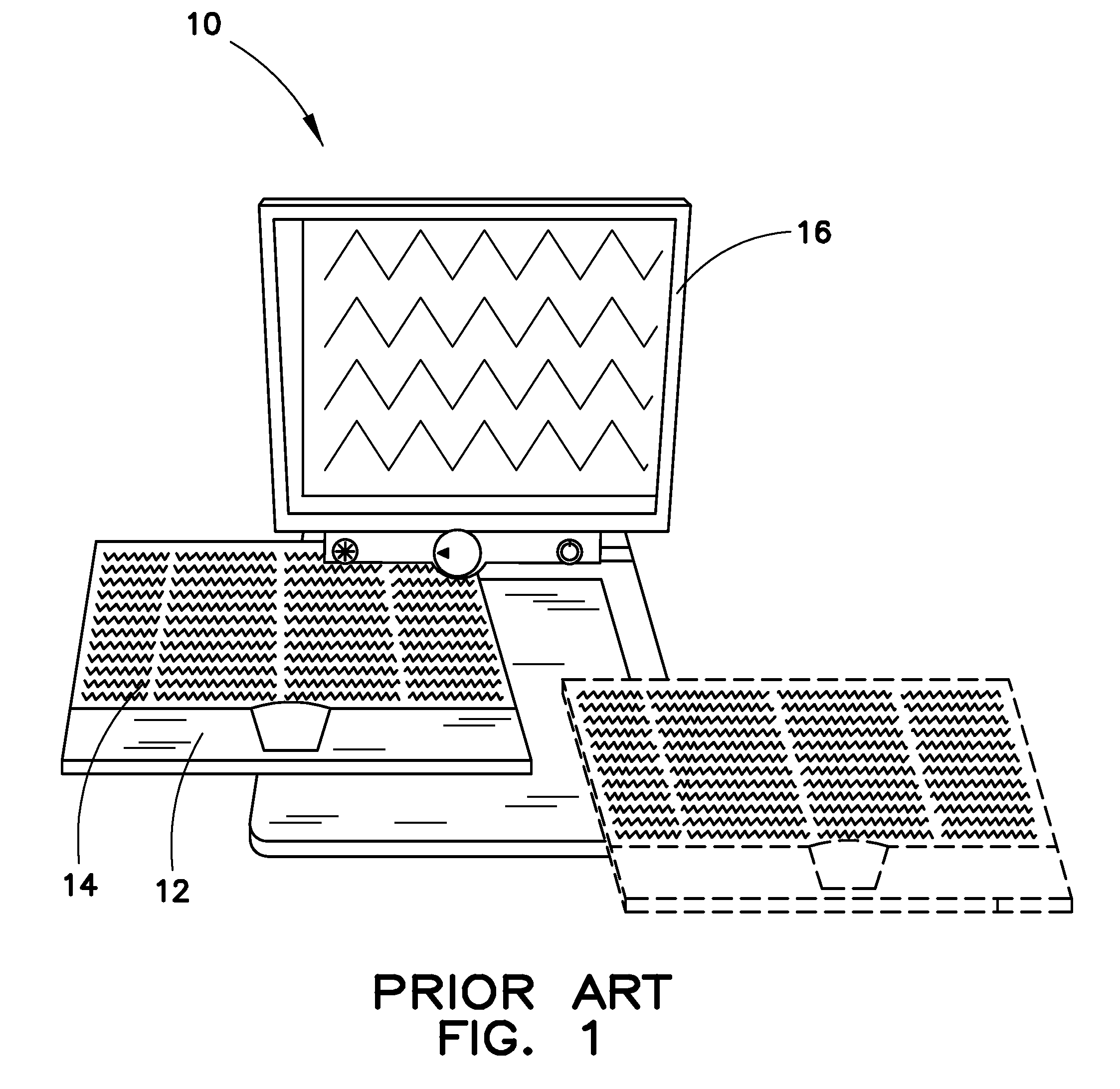
Currently, in order to accommodate objects of different sizes, the footprint required for complete movement range of the working platform is excessively large and the movement of the platform is cumbersome.
Maneuvering of the working area can be cumbersome.
Such movements of the platform can create multiple sources of frustration for the user.
Further, if the written text placed on a working area has excessively large font size, individual letters of the text may not fit within an image envelope of the camera.
Additionally, users can suffer from “motion sickness” due to sudden movements of the work area which can cause dizziness, fatigue, and nausea.
The motion sickness is further worsened when the user selects higher magnification levels where relative motion is more erratic.
Additionally, moving the platform can cause poor posture and excessive restrictions which place undesirable stress on the user's neck, shoulders, elbows and hands.
Such interruptions create additional inefficiencies.
The combination of moving the working area at the same time as writing requires a time consuming learning phase.
In addition, many who are visually impaired also have other physical impairments.
Therefore, a user of the prior art system may be physically unable to move the working area with one arm while writing with the other.
These required manual movements of the working area while viewing images of the user writing can be cumbersome.
This also creates inefficiencies as well as inconveniences.
Also, for persons with multiple impairments near simultaneous manipulation of the work area and performing other tasks, e.g., contrast adjustment, can be cumbersome to nearly impossible.
However, magnified images and auxiliary material are displayed on split screens which detrimentally and substantially reduce the size of the displayed work area.
Current image magnification systems lack effective methods and hardware to update firmware installed on the image magnification system.
Further, when the image magnification system is not operating properly, diagnosing and repairing hardware malfunctions can require multiple visits by a technician to the system.

Method used


Image

  • System for multi-media image magnification
  • System for multi-media image magnification
  • System for multi-media image magnification

Examples


Embodiment Construction

[0028]The embodiments in accordance with the present teachings described below are not intended to be exhaustive or to limit the present teachings to the precise forms disclosed in the following detailed description. Rather, the embodiments are chosen and described so that others skilled in the art may appreciate and understand the principles and practices of the present teachings.

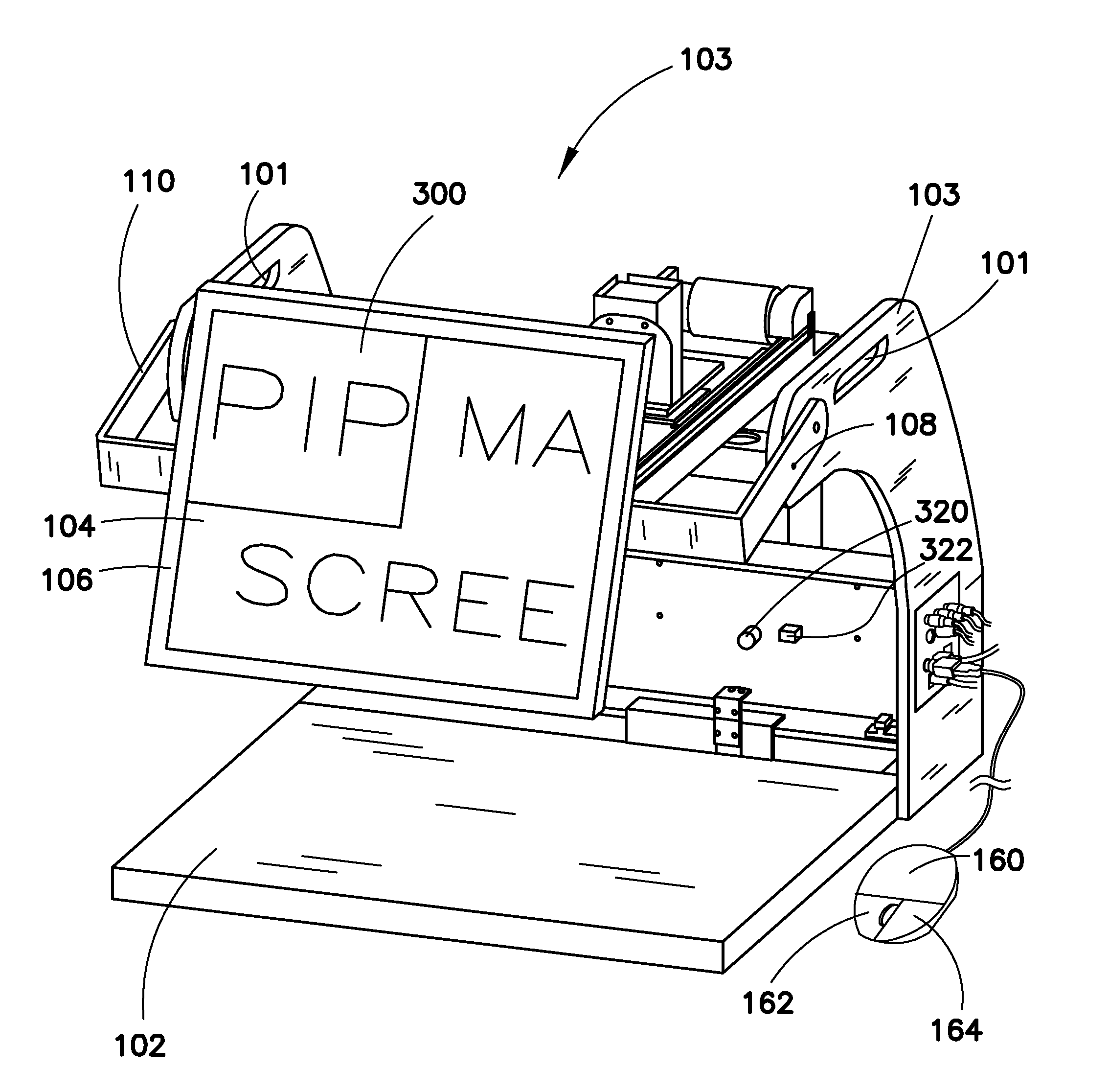
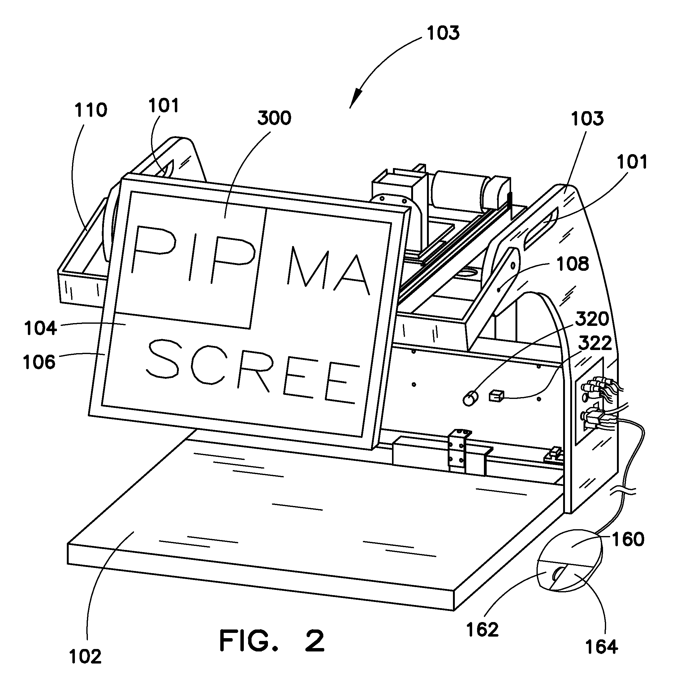
[0029]Referring to FIGS. 2-3, perspective views of the vision magnification system 100 according to the present teachings are shown. Lifting handles are formed by cutouts 101 in L-shaped supports 103. A stationary work area 102 supports objects (not shown). A magnified image 104 is shown on monitor 106 by electronic circuitry 120. The monitor 106 is held by monitor bracket arms 108 coupled to supports 103 which allows the monitor to be tilted upward and downward about a pivot arm 110 defined by the length of monitor bracket arms 108. It is envisioned that the object 14 is either affixed to the stationary w...


PUM


Abstract

A vision magnification system includes a fixed work area, a camera, and drive mechanism capable of moving the camera in at least one direction. The vision magnification system provides a magnified image of an object for viewing by a user and is particularly useful for individuals having impaired vision. A control device includes a pointing device, to control movement of the camera in a direction provided by the user, and a tracking device, which can be coupled to a writing instrument to control movement of the camera when the user uses the writing instrument.

Description

RELATED APPLICATIONS[0001]The present invention claims priority to the U.S. Provisional Patent Application Ser. No. 60 / 988,265 filed Nov. 15, 2007, the entirety of which is incorporated herein by reference.FIELD OF THE INVENTION[0002]The present invention generally relates to an image magnification system, more particularly to an image magnification system for a visually impaired person.BACKGROUND[0003]Image magnification systems are used to magnify a variety of objects. An example is a system used for magnifying images of a working area with an object resting on the working area, where the object is too small to view for persons with normal vision. Another example is a system for magnifying images of written material for visually impaired persons.[0004]Currently, image magnification systems for visually impaired persons can include a stationary color camera and a working area moveable in two dimensions. The camera is positioned to receive images either directly from a targeted view...

Claims


Application Information

Patent Timeline
IPC IPC(8): H04N5/262
CPCH04N7/18
Inventor CURTIN, TIMOTHY M.ROBERTS, MICHAEL J.
Owner EITAC SOLUTIONS GRP
Learn More