Camera control method for vehicle number plate recognition

a technology of vehicle license plate recognition and control method, which is applied in the direction of television system, instrument, and television system scanning details, etc., can solve the problems of deteriorating image quality, affecting the quality of license plate image, and affecting the accuracy of license plate recognition

Inactive Publication Date: 2009-06-25
SAFEOK +1
View PDF7 Cites 51 Cited by
  • Summary
  • Abstract
  • Description
  • Claims
  • Application Information

AI Technical Summary

Benefits of technology

[0011]The entire control is done through 3 steps. The first step is to build up a lookup table of electronic shutter speed and gain level to generate images of various brightness levels and archive the created lookup table on to a memory of a camera. The second step is to calculate the average value of image brightness and write the multiple parameters of electronic shutter speed and gain level that match with the calculated average brightness value in the lookup table to a camera control register. The third step is to output series of images of various brightness that are captured under various shutter speeds and gain levels by the control from the camera register.
[0012]This development is to generate series of images with various brightness instantly by adjusting shutter speed and gain level of each frame to avoid recognition failure due to inadequate (too bright or too dark in recognizing numbers in a p

Problems solved by technology

Especially with license plate recognition system on mobile unit (ex. a patrol car) can be easily disturbed and make errors in recognizing numbers due to the continuous and instant change of brightness in the scenery (ex. a car in an alleyway between buildings, a car in tree shade, a car behind a big truck, etc.) If a license plate is exposed to sun lights dire

Method used


Image

  • Camera control method for vehicle number plate recognition
  • Camera control method for vehicle number plate recognition
  • Camera control method for vehicle number plate recognition

Examples


Embodiment Construction

[0019]With referring to following figures, it describes how the development works in detail.

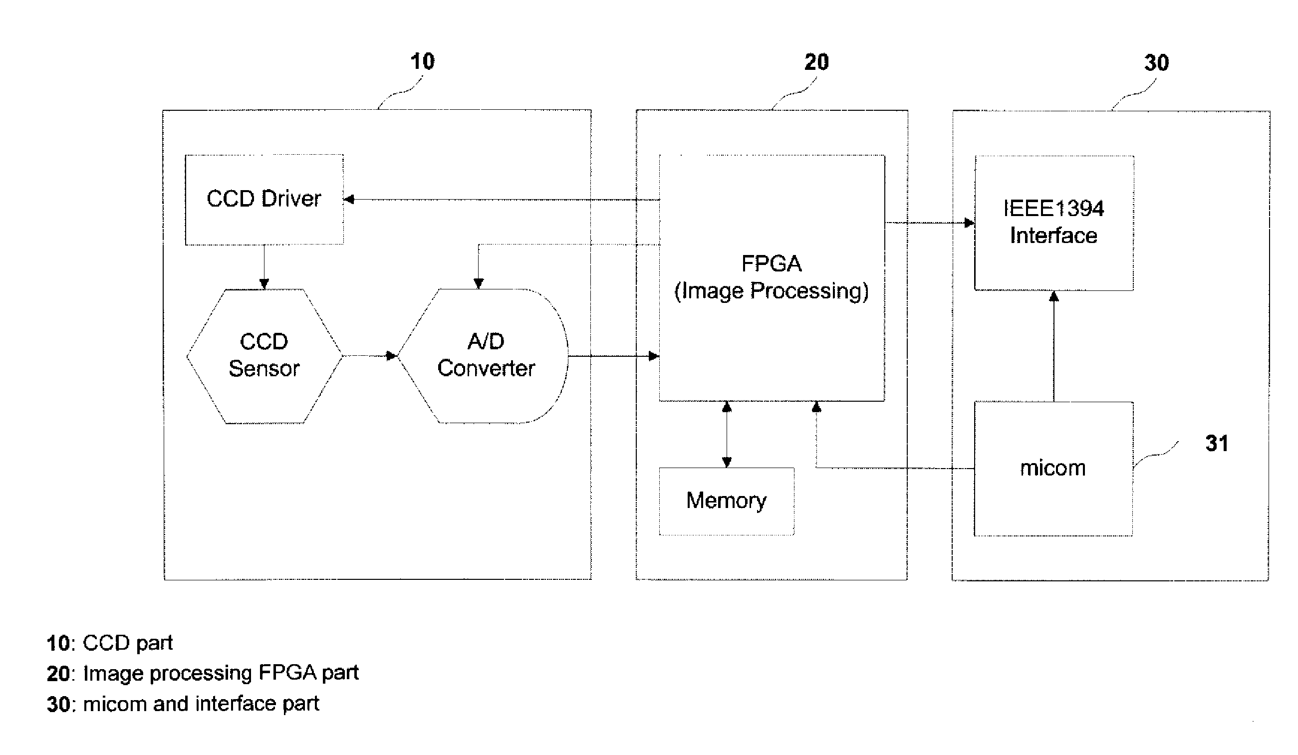
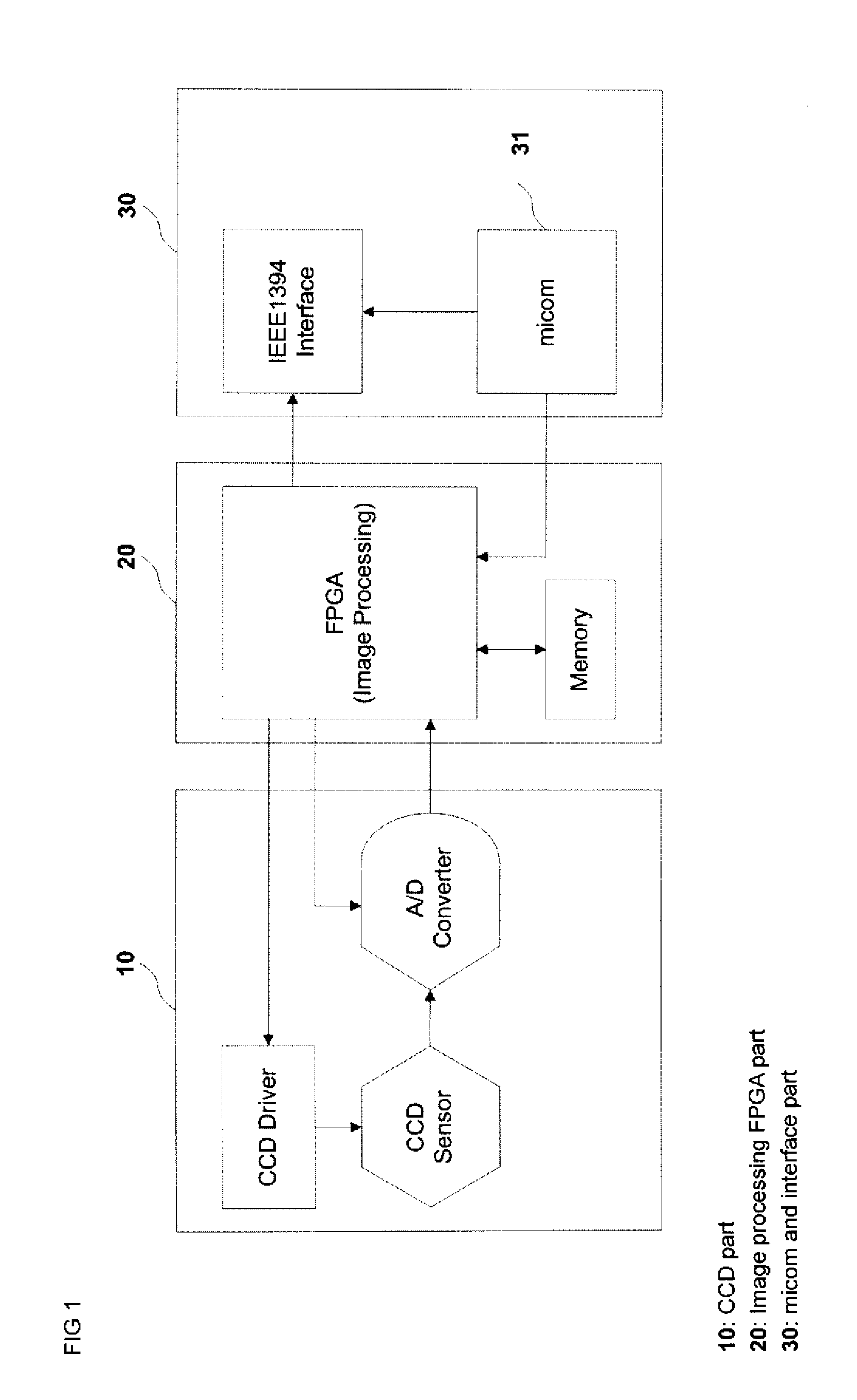
[0020]FIG. 1 is a block diagram of a camera. A progressive-scan CCTV camera functions as the block diagram.

[0021]FIG. 1 block diagram is of a progressive camera that captures images under progressive scanning method and outputs the captured images through IEEE1394 interface. FIG. 1 camera is composed of 3 major parts including CCD part (10), FPGA part (20), and micom control & interface part (30). CCD part (10) is to capture analog light signal and convert it into digital electric signal. This part has CCD (Charge Coupled Device) sensor, CCD driver, and A / D (Analog / Digital) converter. Once CCD driver runs CCD, CCD sensor converts light signal into electric signal and inputs electric signal to A / D converter. A / D converter converts analog signal into digital signal and outputs digital signal to next part.

[0022]FPGA part (20) is to process digital signal into video signal under progressive scann...


PUM


Abstract

This development is about the camera control method for a vehicle license plate recognition system. In detail, it is about the applying variable shutter speed and gain level per image frames that are captured through a CCTV camera of vehicle license plate recognition system. The entire control is done through 3 steps. The first step is to build up a lookup table of electronic shutter speed and gain level to generate images of various brightness levels and archive the created lookup table on to a memory of a camera. The second step is to calculate the average value of image brightness and write the multiple parameters of electronic shutter speed and gain level that match with the calculated average brightness value in the lookup table to a camera control register. The third step is to output series of images of various brightness that are captured under various shutter speeds and gain levels by the control from the camera register. This development is to get series of images with various brightness instantly by adjusting shutter speed and gain level of each frame to avoid recognition failure due to inadequate (too bright or too dark in recognizing numbers in a plate) image frame in harsh conditions such as strong sun lights or fluctuating brightness, which may confuse camera in controlling shutter speed and gain level for getting proper images to recognize.

Description

CROSS-REFERENCE TO RELATED APPLICATIONS[0001]The present application claims priority to Korean Patent Application No. 10-2007-0134773 entitled CAMERA CONTROL METHOD FOR VEHICLE NUMBER PLATE RECOGNITION filed on Dec. 21, 2007.STATEMENT RE: FEDERALLY SPONSORED RESEARCH / DEVELOPMENT[0002]Not ApplicableBACKGROUND[0003]1. Technical Field[0004]This development is about control method for a CCTV camera of a vehicle license plate recognition system. In detail, it is to control electronic shutter speed and gain level of a CCTV camera to get an image of adequate brightness for accurate recognition.[0005]2. Related Art[0006]Generally, license plate recognition system recognizes plate numbers by comparing brightness difference on the image of a license plate. For the license plate recognition system, the most important aspect is to capture a high quality and bright-enough image for successful recognition. In most cases, license plate recognition system uses a progressive-scan camera, which does ...

Claims


Application Information

Patent Timeline
IPC IPC(8): G06K9/00H04N5/335
CPCG06K9/00771H04N5/2356H04N5/2352G06K2209/15G06V20/52G06V20/625H04N23/72H04N23/743
Inventor SON, SEUNG NAM
Owner SAFEOK
Why Eureka
Try Eureka