Device for Securing an Implant to Tissue

a technology for securing implants and tissue, applied in the field of implants, can solve problems such as reduced mobility, spinal nerve roots compression, and pain or limited physical mobility of people, and achieve the effects of reducing mobility, and improving the quality of li

Inactive Publication Date: 2009-06-25
PIONEER SURGICAL TECH INC
View PDF50 Cites 338 Cited by
  • Summary
  • Abstract
  • Description
  • Claims
  • Application Information

AI Technical Summary

Problems solved by technology

A variety of spinal conditions including, for example, trauma, deformity, disease, or other degenerative conditions, may result in a person experiencing pain or limited physical mobility.
This pain and reduced mobility is often attributed

Method used


Image

  • Device for Securing an Implant to Tissue
  • Device for Securing an Implant to Tissue
  • Device for Securing an Implant to Tissue

Examples


Embodiment Construction

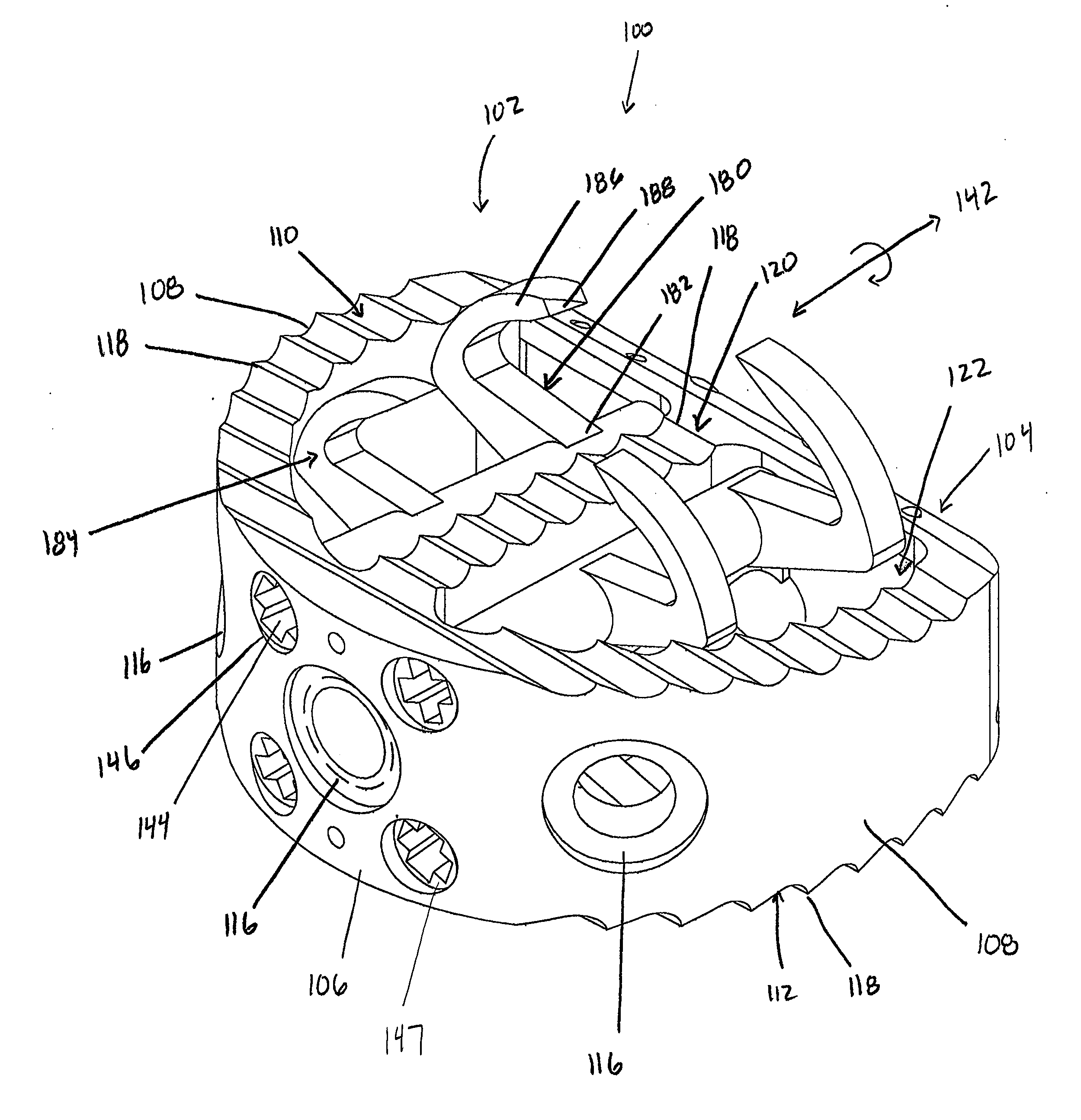
[0043]With reference to FIGS. 1-31, an implant device is shown configured in accordance with various aspects of the invention for being implanted within the spine 6 between adjacent vertebral bodies 10 and secured to at least one of those bodies 10. Further contemplated embodiments include artificial discs, annulus plugs, and other implants, such as those described in U.S. Patent Application Publication No. 2006 / 0129238 to Paltzer, U.S. Patent Application Publication No. 2007 / 0282441 to Stream et al., and U.S. Patent Application Publication No. 2008 / 0103598 to Trudeau et al., which are hereby incorporated in their entirety herein.

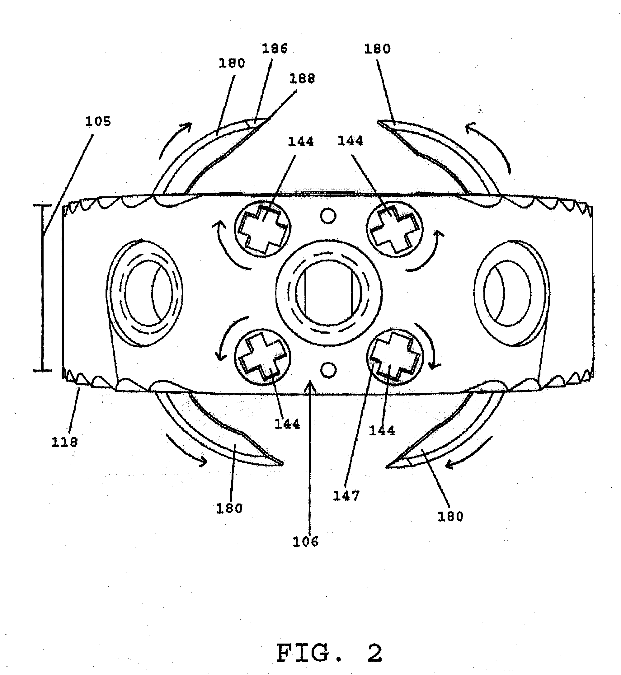
[0044]With reference to FIGS. 1-8, the implant device 100 is shown in accordance with one aspect of the invention. The implant device 100 includes an implant body 102, a rotatable portion 140 and a piercing portion 180 extending from the rotatable portion 140. The rotatable portion 140 and piercing portion 180 can be arranged in a compact orientation, as sh...


PUM


Abstract

An implant device is provided for implantation within an intervertebral space between adjacent vertebrae comprising an implant body, a rotatable portion and a piercing portion configured to pierce the adjacent vertebra.

Description

CROSS REFERENCE TO RELATED APPLICATIONS[0001]This application claims the benefit of the filing date of U.S. Provisional Application 60 / 990,809, which is hereby incorporated in its entirety herein.FIELD OF THE INVENTION[0002]The invention relates to implant devices for implantation within an intervertebral space and fixation to the adjacent vertebrae.BACKGROUND OF THE INVENTION[0003]The spine is the central support column for the human body. It includes a series of vertebrae and intervertebral discs between adjacent vertebrae. The vertebrae are formed of hard bone while the intervertebral discs comprise a comparatively soft annulus and nucleus. The intervertebral discs help to absorb pressure, distribute stress, and keep adjacent vertebrae from grinding against each other.[0004]A variety of spinal conditions including, for example, trauma, deformity, disease, or other degenerative conditions, may result in a person experiencing pain or limited physical mobility. This pain and reduced...

Claims


Application Information

Patent Timeline
IPC IPC(8): A61F2/44A61B17/70
CPCA61B2017/0256A61F2/4465A61F2/447A61F2/4611A61F2002/30112A61F2002/30579A61F2230/0004A61F2002/3082A61F2002/30841A61F2002/30904A61F2002/4627A61F2002/4628A61F2002/30772
Inventor JANOWSKI, BRIANKOVARIK, JOHNDEPAS, WADETRUDEAU, JEFFREY
Owner PIONEER SURGICAL TECH INC
Why Eureka
Try Eureka