Ergonomic handle design applicable to many hand held implements

a technology of ergonomic handle and handle, applied in the field of ergonomic handle design, can solve the problem of little to the artist's creative ability, and achieve the effect of enhancing the comfort ability of human body parts during us

Inactive Publication Date: 2009-07-02
HAGEMANN TED
View PDF8 Cites 3 Cited by
  • Summary
  • Abstract
  • Description
  • Claims
  • Application Information

AI Technical Summary

Benefits of technology

[0030]Two canted handle adjustments aid greatly in the operation of said ergonomic handle. However, the distorted handle appendage end as a solid body, by turning one part relative to another about the main axis of the tool body greatly induces human body parts comfort ability during usage. This said ergonomic handle is the appendage extension from the shoulder of the brush head. The handle extends away from the brush head in the same axis as the head at a predetermined point the appendage forms an approximate downward angle between 20 and 75 degrees the optimum is 40 to 45 degree bend in the appendage. Refer to drawings. The same extended appendage is canted outward at 5 to 35 degree angle with 18 to 25 degrees being optimum. Further more, this said invention also forms a twist of the outward canted appendage between 5 and 35 degrees with 18 to 25 degrees being optimum for this inventor.

Problems solved by technology

This also does little to the artist ability to be creative.

Method used


Image

  • Ergonomic handle design applicable to many hand held implements
  • Ergonomic handle design applicable to many hand held implements
  • Ergonomic handle design applicable to many hand held implements

Examples


Embodiment Construction

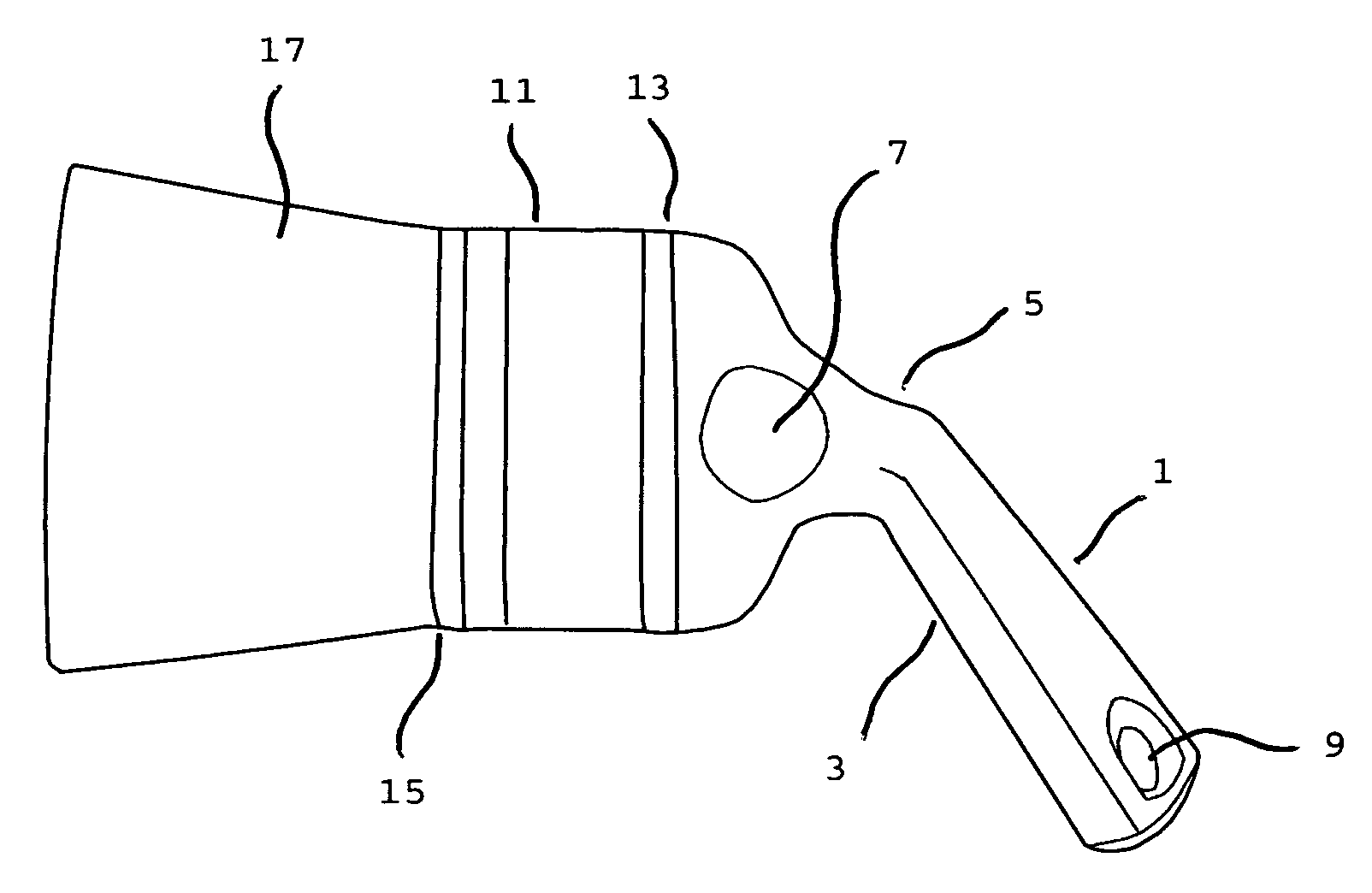
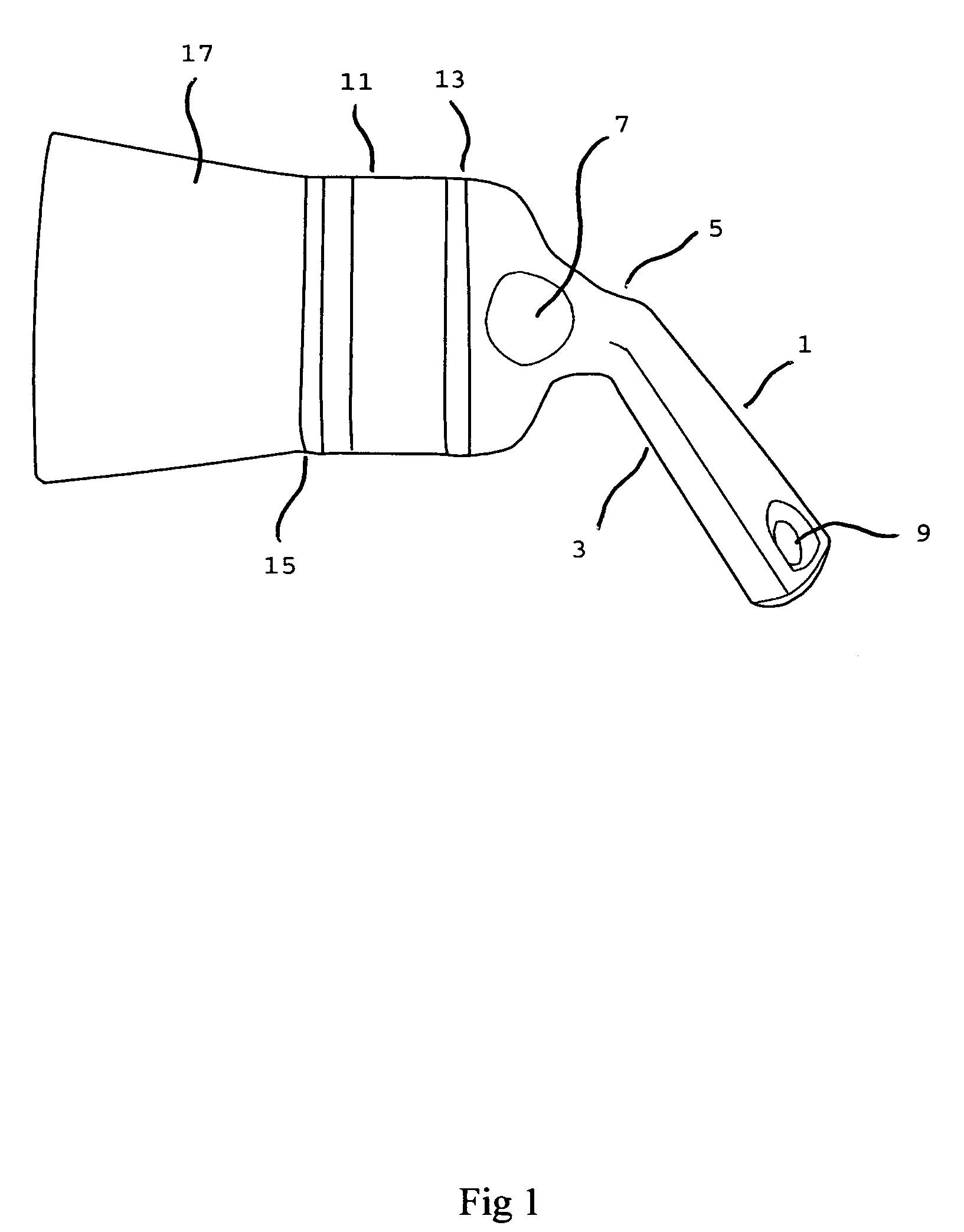
[0044]This said invention ergonomic handle FIG. 1, 1 is manufactured by plastic injected mold process. The furrel FIG. 1, 11, 15 and natural bristles FIG. 1, 7 of the brush are made in conventional means. The said invention handle will be plastic injected by plastic injection machines. The mold will be manufactured to dimension specification set fourth during in the engineering design of the tool mold taking into account of shrinkage for product removal. The tool mold will be injected with plastic to produce said invention. The furrel and natural brush assembly will be stamped by machinery to be clamped to said invention at point FIG. 1, 13. There will be a depression on either side of said handle in the area FIG. 1, 7 for finger control and maneuvering of the brush.

[0045]This said ergonomic handle extends from the shoulder of the brush head. The handle extends away from the brush head in the same axis as the head as usual common know handles commercially available on the market tod...


PUM


Abstract

The ergonomic paint brush handle provides for comfortable 360 degree operation for the user being that there is more than one way to hold and use this ergonomic brush handle. In this said invention I will describe a handle in its application toward the easibility of brushing and painting. The common paint brush handle is very difficult to use for lengths of time and is not ergonomic in design. This said invention will relieve the pains of the hand and fingers by reapplying the hand to a new designed handle based on the over all movement of the hand wrist arm and body.
This said invention takes into account the simultaneous movement of the hand and finger together to operate basic hand tools. The paint brush handle that is described with-in said documents is just one of said tools. The handle extends out on a three dimensional axis to allow a good grip by the right or left hands. The handle allows for the middle, ring and pinky fingers to establish a good grip on said handle. The fore finger and thumb go on each side just below the ferrule on the shoulder of the brush to help guide for control of usage. The angle of the twisted handle allows for easy movement between the palm of the hand and the middle, ring and pinky fingers. The results is a brush with an ergonomic handle that relives all known painting difficulties known with conventional design handles.

Description

BACKGROUND OF INVENTION[0001]This presented ergonomic handle design invention specifically refers to an ergonomically designed ordinary commercially available type paint brush handle.[0002]Years of using hand tools urged this inventor to rethink the hands physical limitations to various tool handle designs presently available in the market place. This said ergonomically designed handle will clearly demonstrate the conformability, easibility and usability with the hands in relationship to the rest of the body.[0003]It is not the intention of said ergonomic invention to include other implement applications this said invention applies. This invention is oriented to the paint brush however mentioned later will be a host of other implements this handle applies. It is important to say that this ergonomic design is applicable to many hand operated levers and implements.[0004]The available paint brush handles that are common to the inventors decades of usage, results in the hand trying to m...

Claims


Application Information

Patent Timeline
Patent Type & Authority Applications(United States)
IPC IPC(8): A46B5/00
CPCA46B5/02Y10T16/476A46B2200/202A46B5/021
Inventor HAGEMANN, TED
Owner HAGEMANN TED
Why Eureka
Try Eureka