Image-acquisition apparatus

a technology of image acquisition and image signal, which is applied in the field of image acquisition apparatus and imageprocessing apparatus, can solve the problems of unbalanced image signal impression, inability to accurately estimate the amount of noise, and inability to generate a sense of unnaturalness in the entire image signal, so as to improve the flexibility of processing, the effect of adjusting the processing speed and changing the size of the prescribed area

Active Publication Date: 2009-07-02
OLYMPUS CORP
View PDF6 Cites 10 Cited by
  • Summary
  • Abstract
  • Description
  • Claims
  • Application Information

AI Technical Summary

Benefits of technology

[0016]In this way, correction coefficients associated with space-variant grayscale conversion are calculated for the image signal on which predetermined signal processing has been performed, and noise reduction and grayscale conversion are performed on the image signal from the image-acquisition device using the correction coefficients. Therefore, it is possible to reduce the sense of unnaturalness caused by a difference in the impression of noise in different enhanced areas when space-variant grayscale conversion is carried out. Furthermore, it is possible to perform highly accurate noise reduction since noise reduction is performed on the image signal from the image-acquisition device.
[0107]The present invention has an advantage in that a uniform impression of noise is provided in the entire image signal even when grayscale conversion is performed by performing grayscale conversion and noise reduction in a balanced manner.

Problems solved by technology

However, since the change in the amount of noise in each area differs, there is a problem in that the impression of noise in the entire image signal becomes unbalanced.
However, when space-variant grayscale conversion is performed, there is a problem in that the amount of noise cannot be accurately estimated because the change in the amount of noise in each area differs even when the signal-value level is the same.
Therefore, a sense of unnaturalness is generated in the entire image signal.

Method used


Image

  • Image-acquisition apparatus
  • Image-acquisition apparatus
  • Image-acquisition apparatus

Examples


first embodiment

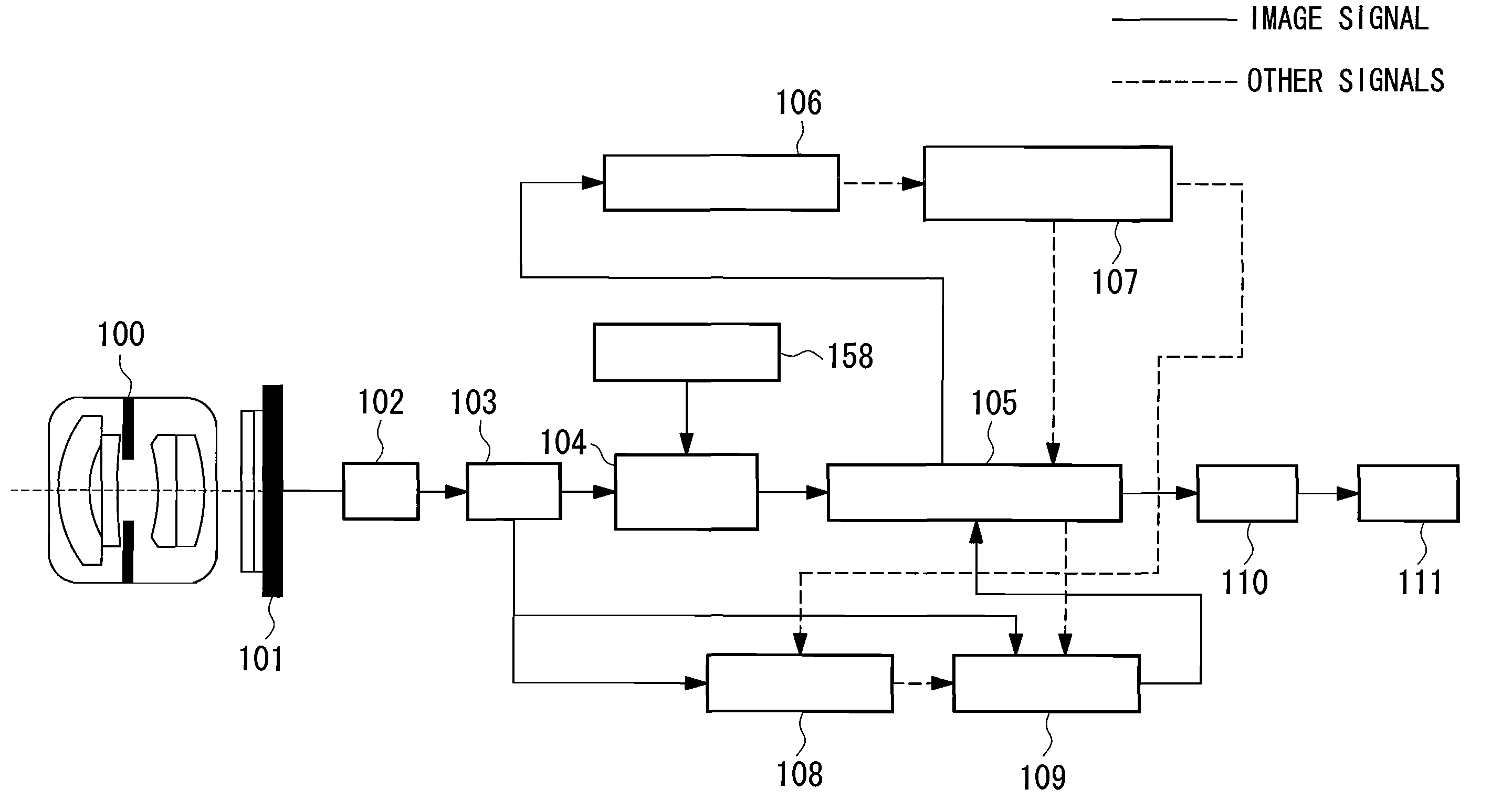
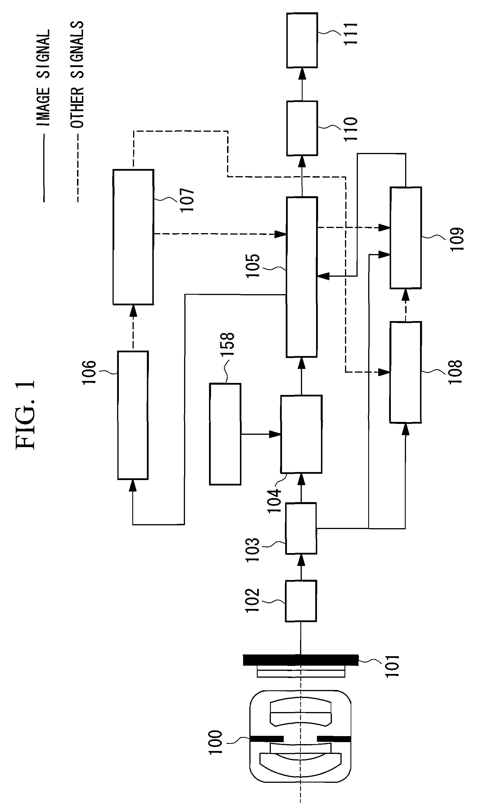
[0171]FIG. 1 is a block diagram of an example configuration of an image-acquisition apparatus according to a first embodiment of the present invention. In FIG. 1, a lens system 100 and a CCD 101 are disposed in this order along the optical axis. The CCD 101 is connected to an A / D converter 102. The A / D converter 102 is connected to a buffer 103. The buffer 103 is connected to a reduced-image creating unit 104, a noise estimating unit 108, and a noise reducing unit 109. A reduction-ratio setting unit 158 is connected to the reduced-image creating unit 104. The reduced-image creating unit 104 is connected to a signal processing unit 105. The signal processing unit 105 is connected to a correction-coefficient calculation unit 106, the noise reducing unit 109, and a compressing unit 110. The correction-coefficient calculation unit 106 is connected to a correction-coefficient map buffer 107. The correction-coefficient map buffer 107 is connected to the signal processing unit 105 and the ...

second embodiment

[0242]Next, an image-acquisition apparatus according to a second embodiment of the present invention will be described with reference to the drawings.

[0243]FIG. 18 is a block diagram of the overall structure of the image-acquisition apparatus according to the second embodiment of the present invention.

[0244]The second embodiment has substantially the same structure as the above-described first embodiment. However, the second embodiment differs from the first embodiment in that a signal processing unit 200 is included instead of the signal processing unit 105, a noise estimating unit 208 is included instead of the noise estimating unit 108, a noise reducing unit 209 is included instead of the noise reducing unit 109, and a correction-coefficient multiplication unit 201 is further included.

[0245]Features of the image-processing apparatus according to this embodiment that are the same as those according to the first embodiment will not be described, and mainly differences will be descr...

third embodiment

[0274]Next, an image-acquisition apparatus according to a third embodiment of the present invention will be described with reference to the drawings.

[0275]FIG. 25 is a block diagram of the overall structure of the image-acquisition apparatus according to the third embodiment of the present invention.

[0276]Features of the image-acquisition apparatus according to this embodiment that are the same as those according to the first embodiment will not be described, and mainly differences will be described below. Components that are the same as those according to the first embodiment are represented by the same names and reference numerals.

[0277]In FIG. 25, the signal processing unit 105 is connected to the reduced-image creating unit 104, the noise estimating unit 208, and the noise reducing unit 209. The reduction-ratio setting unit 158 is connected to the reduced-image creating unit 104. The reduced-image creating unit 104 is connected to the correction-coefficient calculation unit 106....


PUM


Abstract

The object is to provide a uniform impression of noise for an entire image signal by performing grayscale conversion and noise reduction in a balanced manner. The signal processing unit performs first signal conversion on an image signal from an image-acquisition device and transfers the processed image signal to a correction-coefficient calculation unit. The correction-coefficient calculation unit calculates, on the basis of the image signal from the signal processing unit, an area correction coefficient for each area used for grayscale conversion of each area. A noise reducing unit uses the area correction coefficients calculated by the correction-coefficient calculation unit to perform noise reduction on the image signal from the image-acquisition device and transfers the processed signal to the signal processing unit. The signal processing unit performs grayscale conversion on the areas of the noise-reduced image signal and transfers the signal to the compressing unit using the area correction coefficients.

Description

TECHNICAL FIELD[0001]The present invention relates to an image-acquisition apparatus and an image-processing apparatus that carry out grayscale conversion and, more specifically, relates to an image-acquisition apparatus and an image-processing apparatus that control noise reduction such that the entire image signal has a uniform impression of noise.BACKGROUND ART[0002]In current digital still cameras and video cameras, the grayscale range (about 10 to 12 bits) of an image signal in input and processing systems is set larger than the grayscale range of the final output signal (normally 8 bits) to prevent degradation of the image quality caused by cancellation of digits during digital signal processing. In such a case, it is necessary to perform grayscale conversion so as to match the grayscale range of an output system, and usually, conversion is performed according to a fixed grayscale characteristic for a typical scene.[0003]However, when an image signal having a grayscale range t...

Claims


Application Information

Patent Timeline
Patent Type & Authority Applications(United States)
IPC IPC(8): H04N5/213
CPCH04N1/409H04N5/217G06T2207/20192G06T5/003G06T2207/10024G06T5/002H04N23/81
Inventor ARAGAKI, HIDEYA
Owner OLYMPUS CORP
Why Eureka
Try Eureka