Hybrid high voltage DC contactor with arc energy diversion

a contactor and high-voltage technology, applied in the field of electric switches, can solve the problems of induced surge of energy, heavy and complex, and prior-art high-power contactors with protected contact elements or by-pass shunts

Inactive Publication Date: 2009-07-02
HONEYWELL INT INC
View PDF9 Cites 46 Cited by
  • Summary
  • Abstract
  • Description
  • Claims
  • Application Information

AI Technical Summary

Benefits of technology

The present invention is related to an electrical power circuit that includes a contactor with movable contacts, an electrical shunt to by-pass current around the contacts, and a pulse control unit to periodically operate the shunt during movement of the contacts. The technical effect of this invention is to improve the performance and reliability of the electrical power circuit by reducing the likelihood of overcurrenting or other electrical arcing events that can occur during normal contactor operation.

Problems solved by technology

The technical problem addressed in this patent is the need for improved contactors that can interrupt high-amperage DC in a reliable, lightweight, and cost-effective way. Prior-art contactors are expensive, heavy, and complex, which makes them unappealing for use in aircraft. The invention aims to provide a solution to this problem by developing a new type of contactor that can handle high-current DC circuits and provide a by-pass shunt to prevent damage from energy surges.

Method used


Image

  • Hybrid high voltage DC contactor with arc energy diversion
  • Hybrid high voltage DC contactor with arc energy diversion
  • Hybrid high voltage DC contactor with arc energy diversion

Examples


Embodiment Construction

[0017]The following detailed description is of the best currently contemplated modes of carrying out the invention. The description is not to be taken in a limiting sense, but is made merely for the purpose of illustrating the general principles of the invention, since the scope of the invention is best defined by the appended claims.

[0018]Broadly, the present invention may be useful for interrupting high-amperage current in a circuit. More particularly, the present invention may provide light-weight shunted contactors to perform such interruption. The present invention may be particularly useful in vehicles such as aircraft.

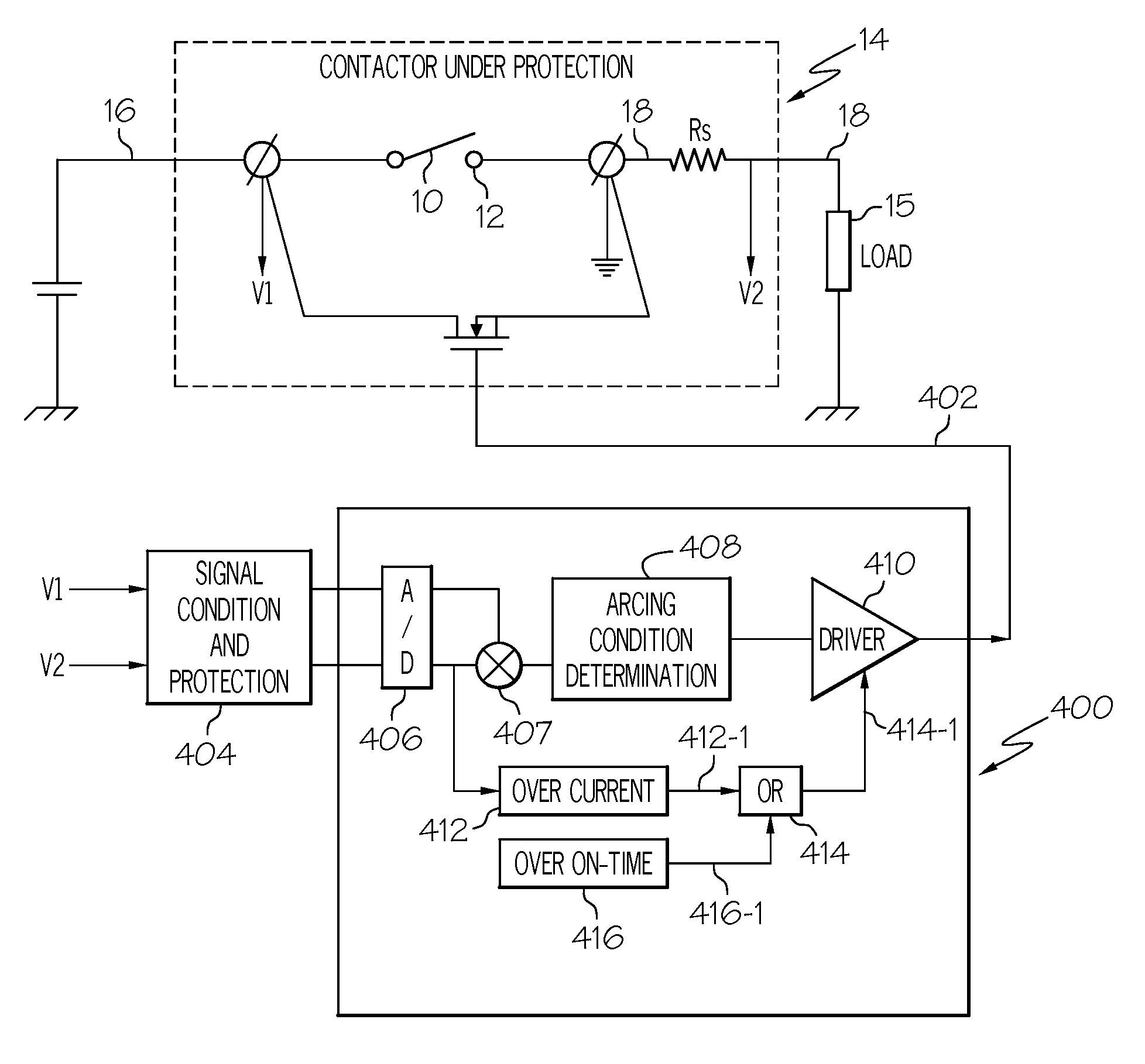
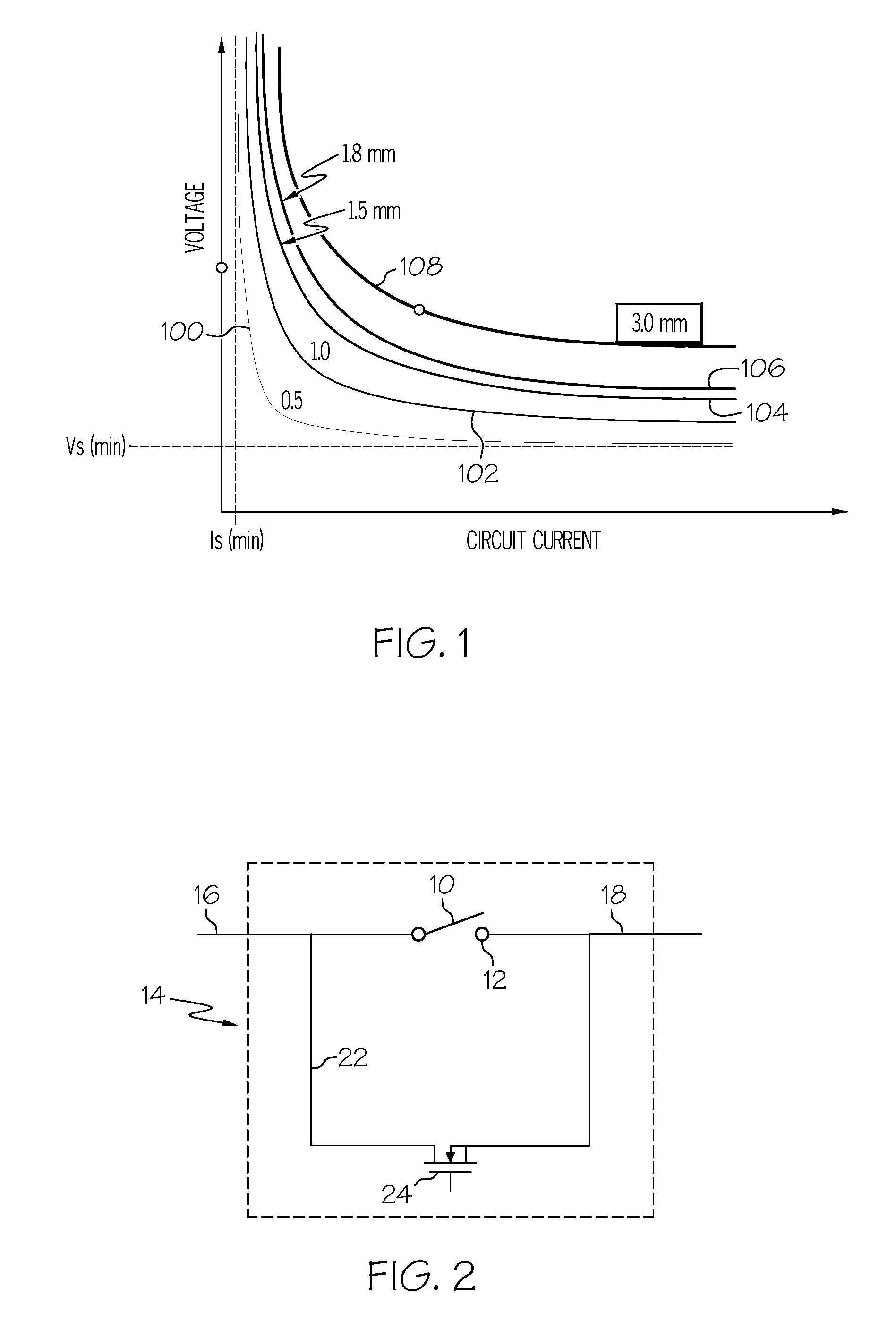
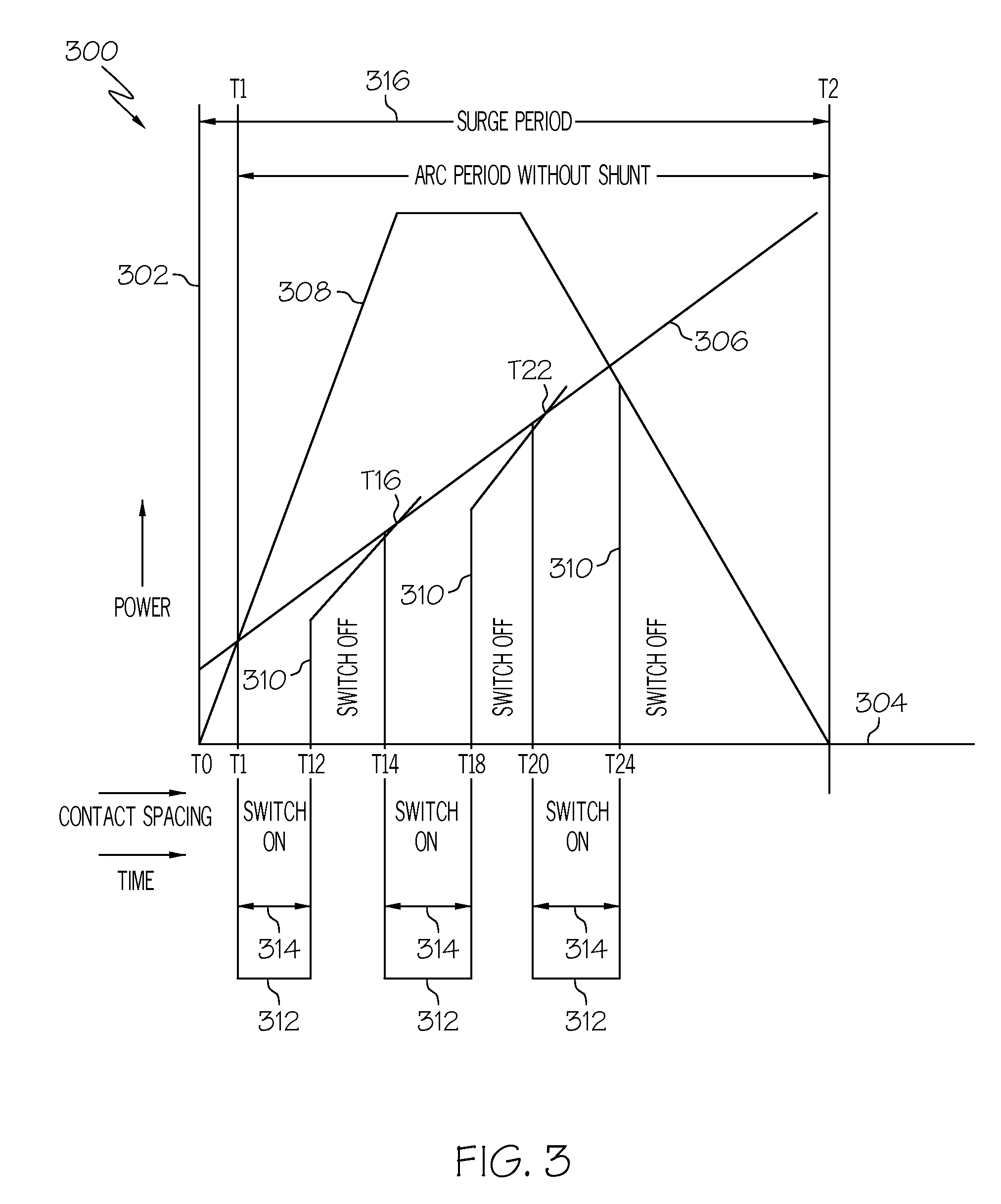
[0019]In contrast to prior-art contactors, among other things, the present invention may provide a pulse-rated shunt for a contactor. The present invention, instead of employing a prior-art steady-state rated shunt for a contactor, may, utilize a lower-rated shunt. The lower-rated shunts may be operated in a series of conducting pulses to reduce or preclude arci...


PUM


Abstract

A contactor may operate to interrupt current in a circuit while the circuit is operating under load. A shunt is provided to by-pass surge power current around contacts to reduce arcing. The shunt includes a solid-state switch that may be operated in a series of pulses during movement of the contacts. The pulse control unit may detect a potential for arcing and then provide for periodic pulsing operation of the shunt. Because the solid-state switch may operate discontinuously, the contactor may be constructed with a switch that is selected on a basis of its pulse rating.

Description


Claims


Application Information

Patent Timeline
Owner HONEYWELL INT INC
Why Eureka
Try Eureka