Performance of ECMP Path Tracing in an MPLS Enabled Network

Active Publication Date: 2009-07-02
AT&T INTPROP I L P
View PDF14 Cites 26 Cited by
  • Summary
  • Abstract
  • Description
  • Claims
  • Application Information

AI Technical Summary

Problems solved by technology

The conventional approaches are typically very time consuming, especially as path complexity between endpoints (e.g., source and destination routers) increases.
For example, these conventional approaches can require in excess of 45 minutes.
These technique

Method used


Image

  • Performance of ECMP Path Tracing in an MPLS Enabled Network
  • Performance of ECMP Path Tracing in an MPLS Enabled Network
  • Performance of ECMP Path Tracing in an MPLS Enabled Network

Examples


Embodiment Construction

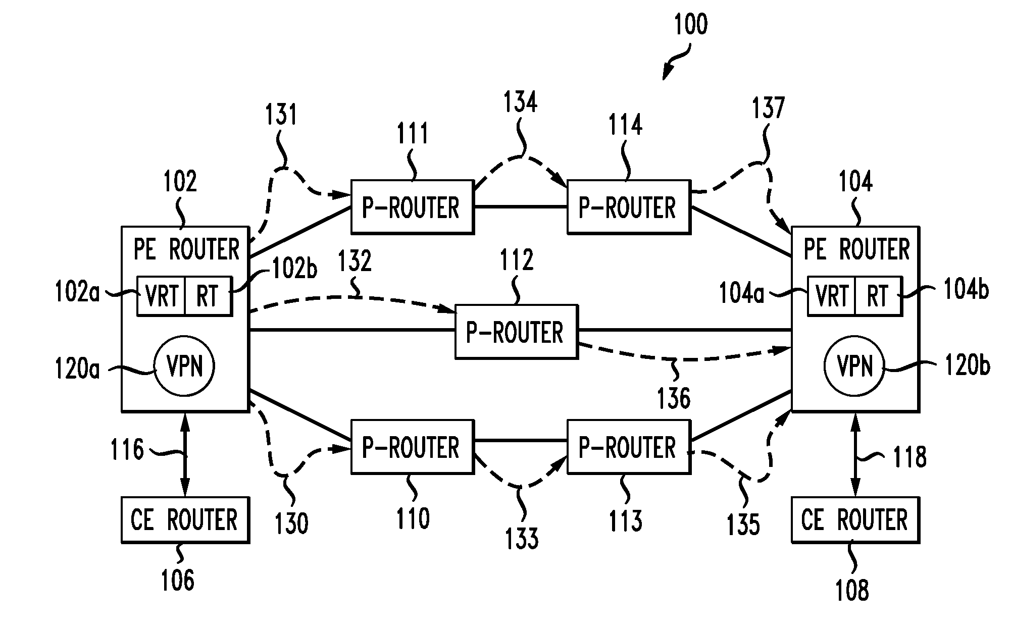
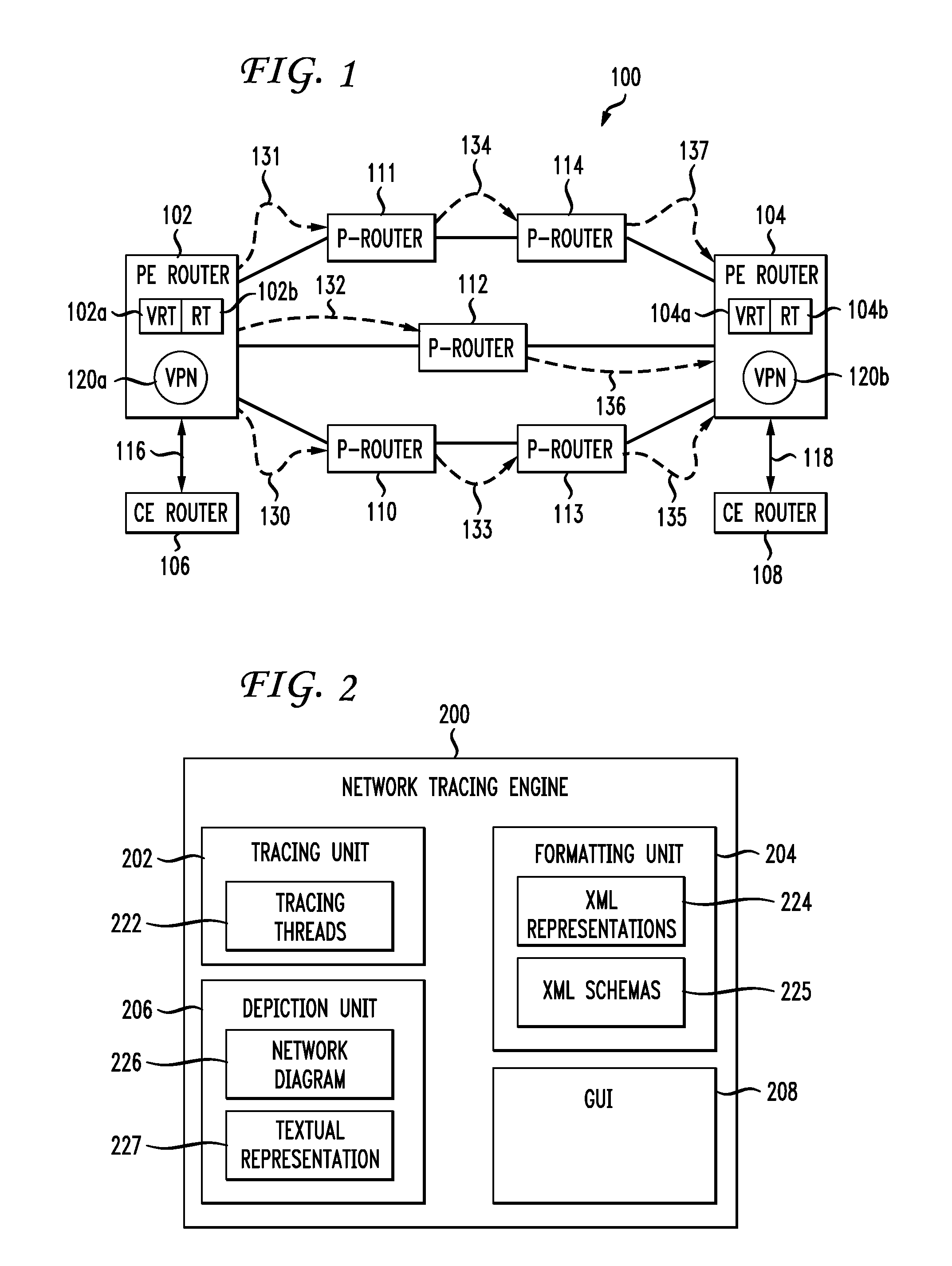
[0009]The preferred embodiments of the present invention are directed to a method, medium, and system for determining a network configuration representation. The preferred embodiments are preferably implemented by a computing device to obtain trace information associated with a plurality of equal cost paths and generate a network configuration representation using the trace information. The trace information is obtained concurrently from a plurality of routers associated with different equal cost paths.

[0010]Obtaining trace information can include obtaining trace information associated with a source router using a parent trace thread and obtaining trace information associated with the plurality of routers associated with different equal cost paths using at least one child trace thread associated with the parent trace thread. Trace information associated with at least one of the plurality of routers associated with different equal cost paths can be reused in response to at least two ...


PUM


Abstract

The preferred embodiments of the present invention are directed to a network tracing engine for tracing and depicting a topology (i.e. a network configuration) of a network using, for example, a network diagram. The network tracing engine preferably queries/telnets to interfaces of routers associated with one or more source-to-destination paths in a network concurrently and independently to ensure proper configuration of the routers and/or to generate a true depiction of a routing configuration without redundantly querying routers.

Description

BACKGROUND OF THE INVENTION[0001]1. Field of the Invention[0002]The present invention is directed to tracing a MPLS enabled network and to graphically depicting a network configuration based on the tracing.[0003]2. Brief Description of the Related Art[0004]Internet Protocol (IP) networks may implement Multi-Protocol Label Switching (MPLS) to ensure that packets in a selected flow follow the same route through the network's backbone. In such networks, data packets include routing information that determines the path the data packet follows through the network. To achieve this, MPLS routers attach labels containing forwarding information to data packets before the data packets leave the routers. These MPLS routers are generally located at the periphery of the network and generally perform packet analysis and classification before data packets enter the core of the network. The Label Switch Routers (LSRs) are generally located within the core of the network. These LSRs examine labels a...

Claims


Application Information

Patent Timeline
IPC IPC(8): H04L12/28H04L45/02H04L45/50
CPCH04L41/06H04L41/12H04L45/26H04L41/5074H04L45/02H04L41/22H04L45/50H05K999/99
Inventor WASHBURN, RAYMOND
Owner AT&T INTPROP I L P
Why Eureka
Try Eureka