
Butterfly network for permutation or de-permutation utilized by channel algorithm

a channel algorithm and network technology, applied in the field of network permutation or depermutation, can solve the problem that none of the prior art references applies the concept in the field of channel coding permutation and depermutation

Inactive Publication Date: 2009-07-02
NAT CHIAO TUNG UNIV
View PDF31 Cites 2 Cited by
  • Summary
  • Abstract
  • Description
  • Claims
  • Application Information

AI Technical Summary

Benefits of technology

"The present invention provides a butterfly network for channel coding permutation and de-permutation. The network includes columns of nodes connected by edges, and switches that can perform switching operations. The nodes are selected as switches and can be controlled to perform switching operations simultaneously. The technical effect of this invention is to provide a more efficient and effective network for channel coding permutation and de-permutation."

Problems solved by technology

However, none of the prior art references applies the concept in the field of channel coding permutation and de-permutation.

Method used


Image

  • Butterfly network for permutation or de-permutation utilized by channel algorithm
  • Butterfly network for permutation or de-permutation utilized by channel algorithm
  • Butterfly network for permutation or de-permutation utilized by channel algorithm

Examples


Embodiment Construction

[0018]Reference will now be made in detail to the present examples of the invention illustrated in the accompanying drawings. Wherever possible, the same reference numbers will be used throughout the drawings to refer to the same or like portions.

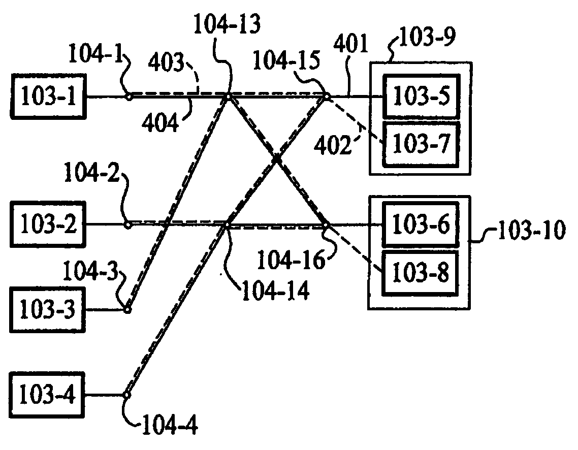
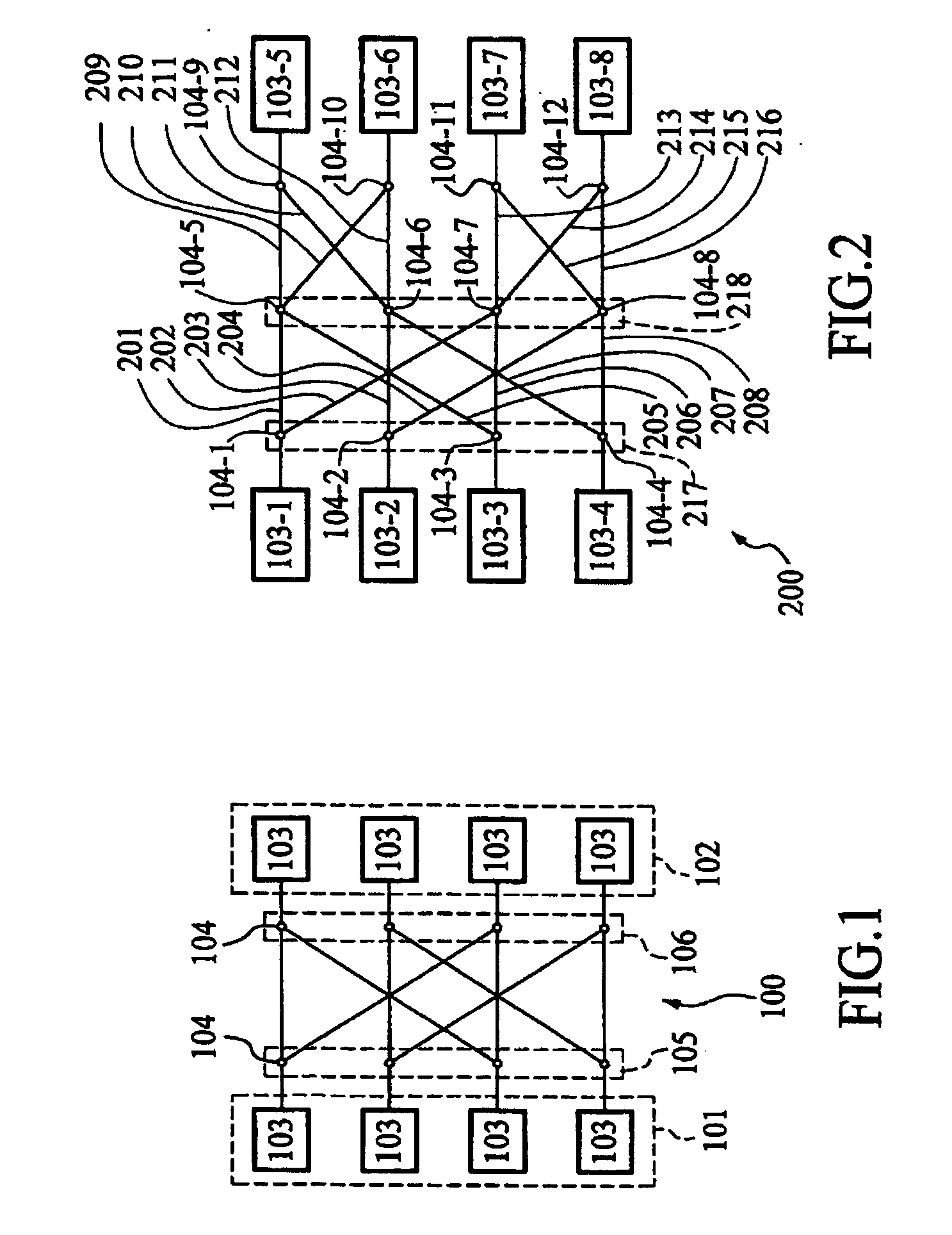
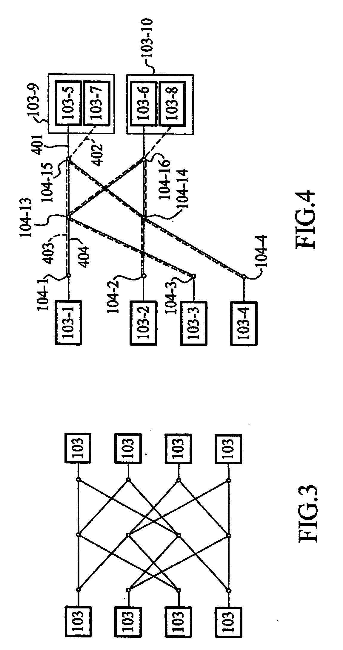
[0019]FIG. 1 is a diagram illustrating a butterfly network (100) according to an example of the present invention. Refer to FIG. 1, a basic structure of the butterfly network (100) may comprise a first side (101) and a second side (102). Each of the first side (101) and second side (102) may have 4 terminals (103). The butterfly network (100) may comprise two columns (105, 106) of nodes (104) located between the first and second sides (101, 102). A first column (105) may interface the first side (101) and a second column (106) may interface the second side (102). Each of the columns (105, 106) may comprise 4 nodes (104), wherein each of the nodes (104) may be connected to a first number of the nodes (104) (e.g. 2) of each of columns adjacen...


PUM


Abstract

A butterfly network for channel coding permutation and de-permutation. The butterfly network may include a first side and a second side, wherein each of the first side and second side has at least one terminal and two or more columns of nodes located between the first and second sides, wherein a first column of the columns may interface the first side, a second column of the columns may interface the second side and each of the columns comprises at least one node, wherein each node of the columns may be connected to a first number of nodes in each of adjacent columns next to the columns, and said first number may be identical for all the nodes in the network, and wherein the nodes which may be selected as switches are concurrently controlled to perform switching operations.

Description

BACKGROUND OF THE INVENTION[0001]The present invention relates to a network for permutation or de-permutation, especially a butterfly network for permutation or de-permutation utilized by channel coding and a channel coding security concept thereof.[0002]Turbo Code (TC), which is an example of the so-called channel coding, was invented in 1993 and can produce a near Shannon limit performance by applying an iterative decoding algorithm. In co-pending U.S. patent application Ser. No. 11 / 176,829 by Zheng et. al., innovative encoder and decoder designs were presented with real-time performance, wherein inter-sequence permutation and intra-sequence permutation are both utilized. Conventionally, many algorithms, e.g. lookup tables, can be used in performing permutations, but they are either complex or inflexible, and a new algorithm is preferred.[0003]A so-called “butterfly network” is used to perform a method to illustrate FFT (Fast Fourier Transform), which is intensively used in the fi...

Claims


Application Information

Patent Timeline
Patent Type & Authority Applications(United States)
IPC IPC(8): H04J3/02
CPCH03M13/00H03M13/033H03M13/1102H03M13/2757H04L1/0066H03M13/2957H04L1/0041H04L1/0045H03M13/2771
Inventor ZHENG, YAN-XIU
Owner NAT CHIAO TUNG UNIV
Learn More