Work seat apparatus

a work seat and seat technology, applied in the field of work seat apparatus, can solve the problem that the operation is not readily performed on the ceiling

Inactive Publication Date: 2009-07-09
HONDA MOTOR CO LTD
View PDF2 Cites 4 Cited by
  • Summary
  • Abstract
  • Description
  • Claims
  • Application Information

AI Technical Summary

Benefits of technology

[0023]In the support shaft, an elastic member that is provided below the seat surface part and that returns the seat part to an original position is preferably disposed between the seat part and the frame. The support shaft is disposed below a seating part. Therefore, there is no risk of, e.g., part of the body of the operator coming into contact with the support shaft.

Problems solved by technology

Operations are not readily performed on the ceiling.

Method used


Image

  • Work seat apparatus
  • Work seat apparatus
  • Work seat apparatus

Examples


Embodiment Construction

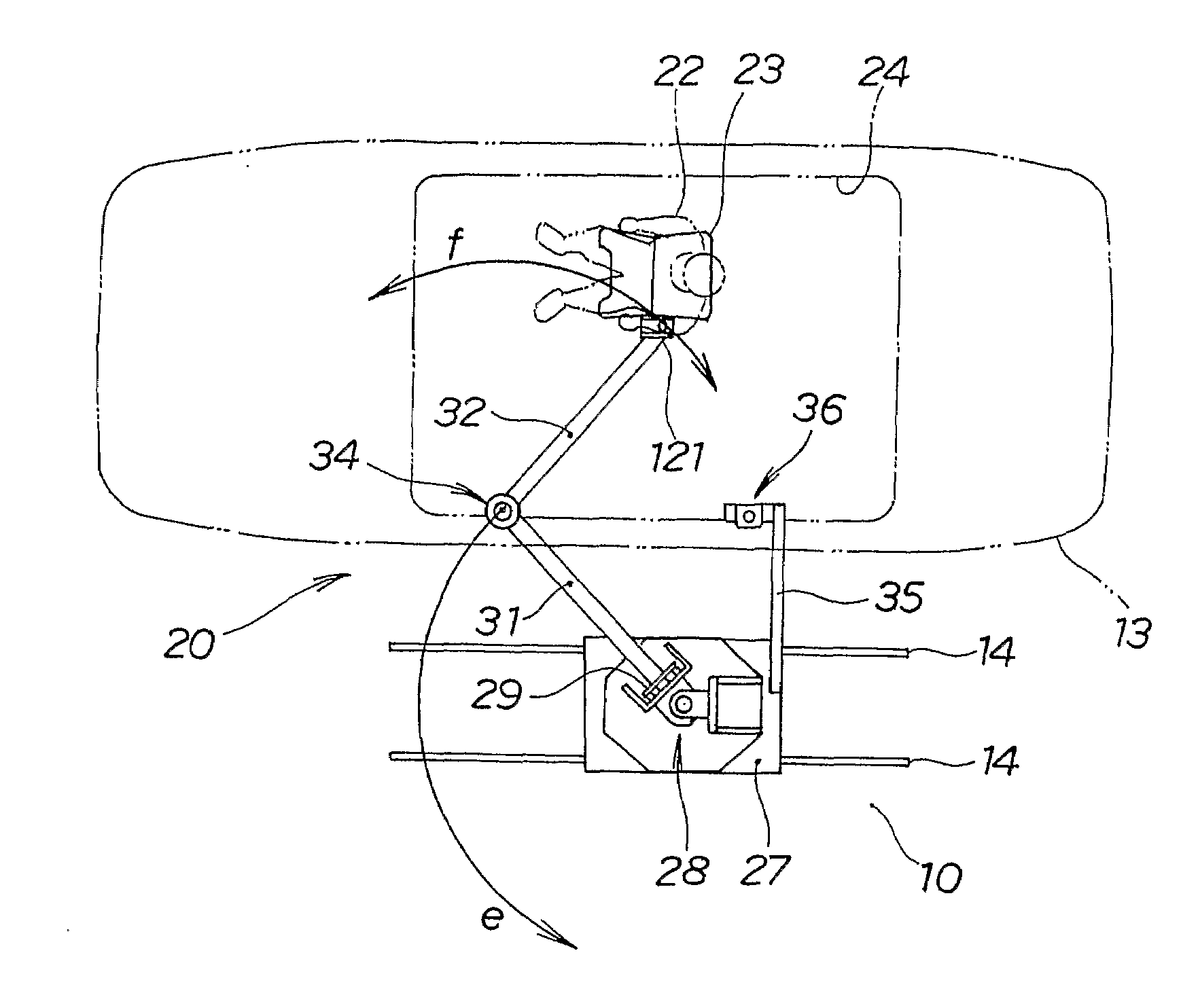
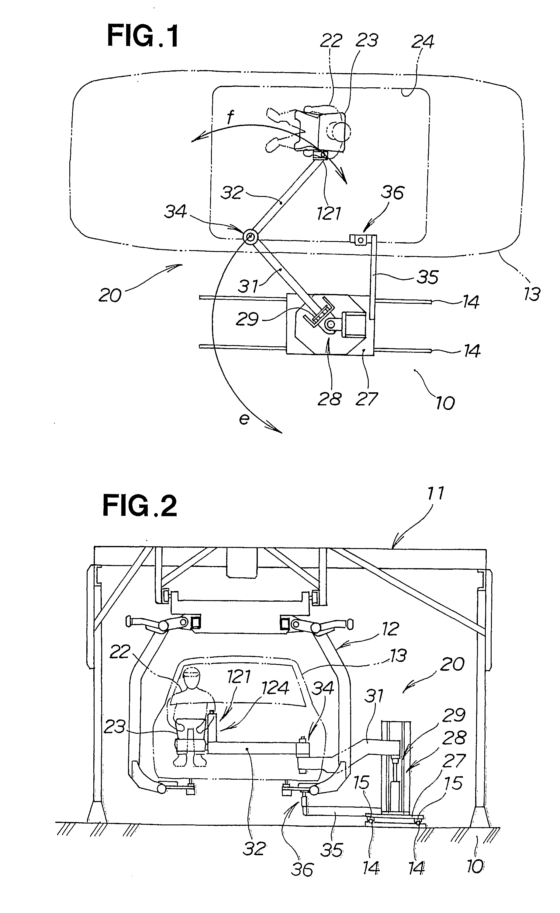
[0043]An overhead conveyer 11 for conveying a vehicle and a conveying hanger 12 that is provided to the overhead conveyer 11 and that is used as a conveying mechanism to convey a vehicle are provided to an automobile assembly line, as shown in FIGS. 1 and 2. A vehicle 13 is mounted on the conveying hanger 12 as a workpiece. In the automobile assembly line, components and the like are attached while the vehicle 13 is moved.

[0044]Rails 14, 14 are disposed to sides of the vehicle 13 along a movement direction of the vehicle 13 above the floor, stage, or other anchoring object 10. A work seat apparatus 20 that is provided for tasks in an interior of the automobile is provided to the rails 14, 14 via wheels 15, 15.

[0045]The work seat apparatus 20 is characterized in comprising a base part 27 provided to an anchoring object 10 in a manner that allows horizontal movement; a rotating support part 28 provided to the base part 27 in a manner that allows rotation about a vertical shaft; a rais...


PUM


Abstract

A work seat apparatus (20) in which an operator (22) can work on a workpiece (13) while seated. The apparatus includes a horizontal first arm part (31) that is raised and lowered by a raising and lowering part (29), and a second arm part (32). The second arm part (32) is rotatably provided to the first arm part via a joint part (34). A seat on which the operator sits is rotatably provided to a distal end part of the second arm part and is readily brought near to an operation position.

Description

TECHNICAL FIELD[0001]The present invention relates to a work seat apparatus in which an operator can perform an operation on a workpiece while sitting.BACKGROUND ART[0002]In a vehicle assembly line, an operator performs operations in a standing posture, a crouching posture, a seated posture while sitting in a seat, or a bent-over posture. A seated posture is preferable for increasing the ease with which tasks are performed. In other words, an operation can comfortably be performed if the operator can perform the operation while seated in a seat. A work seat apparatus for this purpose is disclosed in, e.g., Japanese Patent No, 3241492. The disclosed work seat apparatus shall be described below with reference to FIG. 18 hereof.[0003]A work seat apparatus 200 comprises a pair of travel rails 202, 202 anchored to a ceiling frame 201; a hanger rail 203 hung on the travel rails 202, 202 in a manner that allows movement in a direction perpendicular to the drawing; a slider 204 supported by...

Claims


Application Information

Patent Timeline
Patent Type & Authority Applications(United States)
IPC IPC(8): A47C3/20
CPCB25H5/00A47C9/022B62D65/00
Inventor UEDA, MINORUKONAGAYA, KATSUNORI
Owner HONDA MOTOR CO LTD
Why Eureka
Try Eureka