Charging station

a charging station and charging pole technology, applied in the field of charging stations, can solve the problems of difficult installation of such poles, and achieve the effects of low cost, less prone to errors, and cost-effective installation of charging stations

Inactive Publication Date: 2020-04-16
INNOGY SE
View PDF7 Cites 7 Cited by
  • Summary
  • Abstract
  • Description
  • Claims
  • Application Information

AI Technical Summary

Benefits of technology

[0010]Charging stations for electric vehicles can be designed differently. An essential design form is characterised by a single housing, wherein the housing encloses the charging electronics and is formed as a charging pillar. The second group of designs also has a housing with the charging electronics and a pole next to it, to which the charging cable is attached. In order to keep the costs for the installation of a charging station as low as possible, the aim is to keep the number of different installation processes as low as possible.
[0011]When installing a charging station, the excavation must first be carried out. The foundation must then be laid in the area of the excavation and the electrical connections must be routed through the foundation on the ground side. It has been shown that prefabricated foundation parts as standard components for standard charging stations are particularly cost-effective. These can be manufactured in a standardized, industrial environment and are therefore less prone to errors than foundations that are cast individually on site. In addition, the installation of a prefabricated foundation is considerably faster, so that prefabricated foundations are usually used which are placed in the excavation. The excavation must then be filled in and the charging station mechanically fastened to the foundation. Finally, the electrical installation of the charging electronics must take place inside the charging station.

Problems solved by technology

However, the installation of such a pole is challenging, as large lever forces can occur at the bottom of the pole and the pole must be securely protected against buckling.

Method used


Image

  • Charging station
  • Charging station
  • Charging station

Examples


Embodiment Construction

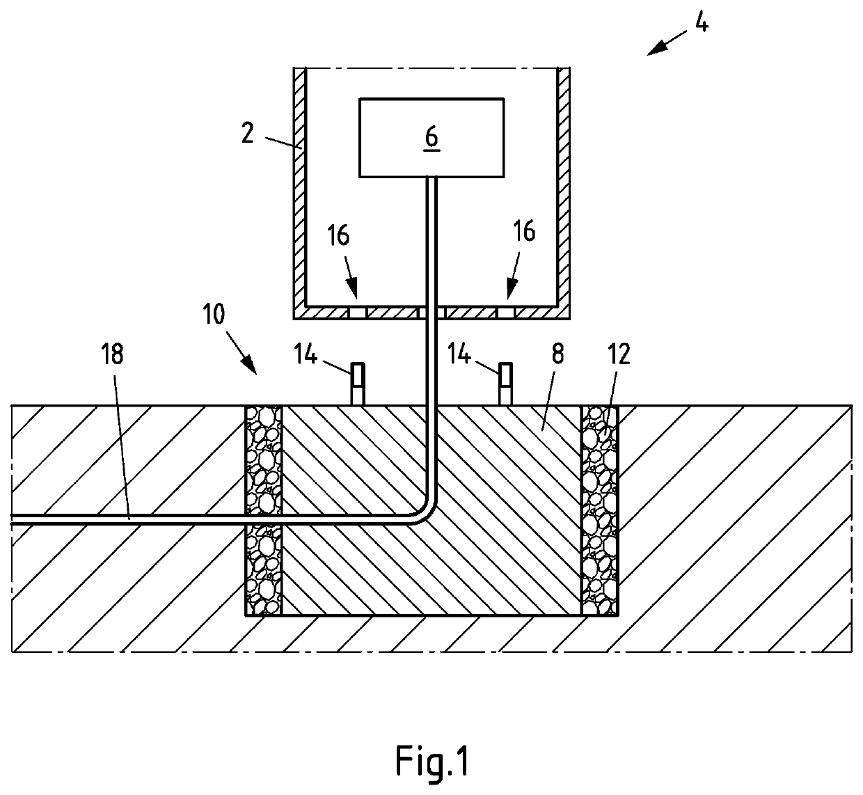
[0042]FIG. 1 shows a schematic cross-sectional view of a housing 2 of a charging station 4 with charging electronics 6. The charging electronics 6 are housed inside the housing 2.

[0043]The housing 2 can be placed on a foundation 8. Foundation 8 is preferably a concrete foundation, in particular a concrete casting. Foundation 8 can be a prefabricated casting, which is inserted into an excavation 10. Then the excavation 10 is filled with a filling material.

[0044]On the foundation 8, protruding screws or bolts 14 are preferably provided on the upper side. The bolts 14 are firmly anchored in the foundation and correspond with openings 16 in the base of the housing 2.

[0045]To install charging station 4, first excavation 10 is made. Then an underground cable 18, which establishes an electrical connection to an electrical supply network, is led into the excavation 10. It is also possible that the underground cable 18 is already in excavation 10.

[0046]Then the foundation 8 is inserted into ...


PUM


Abstract

Embodiments of a charging station for electric vehicles are disclosed. The charging station includes a housing, charging electronics arranged in the housing, a pole arranged next to the housing and leading a charging cable out of the housing, and a foundation supporting the housing. In the charging station, a base plate is arranged between the housing and the foundation for fastening the pole, and the pole is fastened to the base plate.

Description

CROSS-REFERENCE TO RELATED PATENT APPLICATIONS[0001]This patent application is a continuation of PCT / EP2018 / 057756, filed Mar. 27, 2018, which claims priority to German Application No. 10 2017 113 224.4, filed Jun. 16, 2017, the entire teachings and disclosure of which are incorporated herein by reference thereto.FIELD[0002]The subject matter relates to a charging station for electric vehicles comprising a housing, charging electronics arranged in the housing, a pole arranged adjacent to the housing and leading a charging cable out of the housing, and a foundation supporting the housing.BACKGROUND[0003]The distribution of charging stations for electric vehicles will be decisive for the acceptance of electromobility. Electrically powered vehicles require a charging infrastructure, which is why charging stations for electric vehicles are increasingly being installed in public and semi-public spaces. In particular, electric vehicles can be battery-powered electric vehicles (BEV, Batter...

Claims


Application Information

Patent Timeline
Patent Type & Authority Applications(United States)
IPC IPC(8): B60L53/31H02G3/04
CPCH02G3/0493B60L53/31H02G11/003Y02T10/70Y02T10/7072Y02T90/12Y02T90/14B60L53/50B60L53/32
Inventor HELNERUS, STEFANWAFFNER, JÜRGEN
Owner INNOGY SE
Why Eureka
Try Eureka