Transformer Board

a transformer and board technology, applied in the direction of transformer/react mounting/support/suspension, liquid/fluent solid measurement, instruments, etc., can solve the problems of corroding fluid passing through the meter, electric charge presenting a hazard to individuals performing maintenance on the flow meter, undesirable exposure,

Active Publication Date: 2009-07-09
MICRO MOTION INC
View PDF8 Cites 19 Cited by
  • Summary
  • Abstract
  • Description
  • Claims
  • Application Information

AI Technical Summary

Benefits of technology

[0018]Certain terms are used in the following description and claims to refer to particular system components. As one skilled in the art will appreciate, different persons may refer to a component by different names. This document does not intend to distinguish between components that differ in name but not function. The drawing figures are not necessarily to scale. Certain features of the invention may be shown exaggerated in scale or in somewhat schematic form, and some details of conventional elements may not be shown, all in the interest of clarity and conciseness.

Problems solved by technology

The electric charge presents a hazard to individuals performing maintenance on the flow meter.
Such exposure is undesirable when the transformer limits the transducer size or is not designed for the same conditions as the transducer.
For example, the fluid passing through the meter may be corrosive.
While the transducer may be compatible with corrosive conditions, the transformer may not.
In such circumstances, the corrosive fluid may damage the transformer and associated electrical wiring.
However, such a process may be prohibitively costly.

Method used


Image

  • Transformer Board
  • Transformer Board
  • Transformer Board

Examples


Embodiment Construction

[0028]The following discussion is directed to various embodiments of the invention. One skilled in the art will understand that the following description has broad application, and the discussion of any embodiment is meant only to be exemplary of that embodiment, and not intended to intimate that the scope of the disclosure, including the claims, is limited to that embodiment.

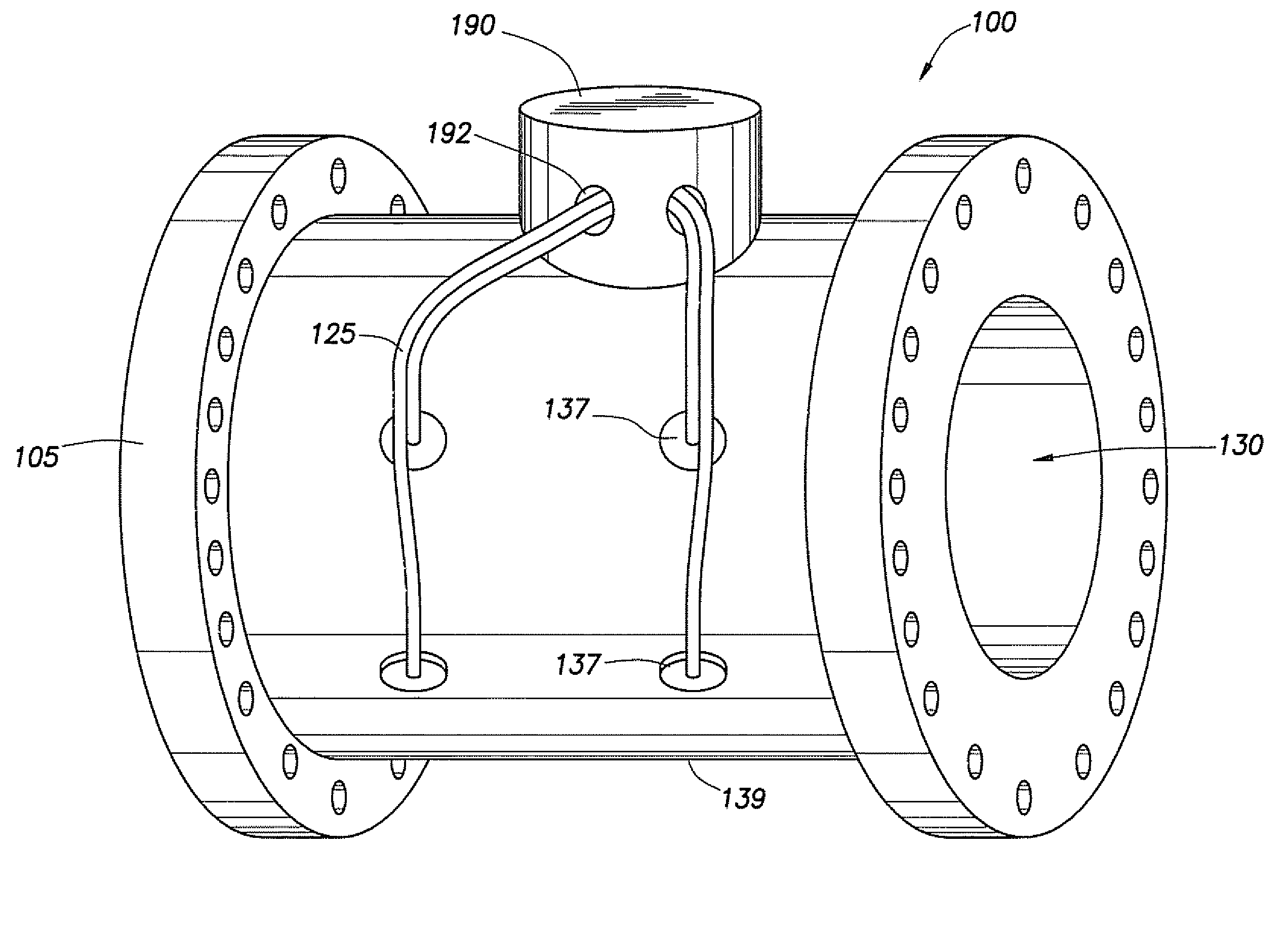
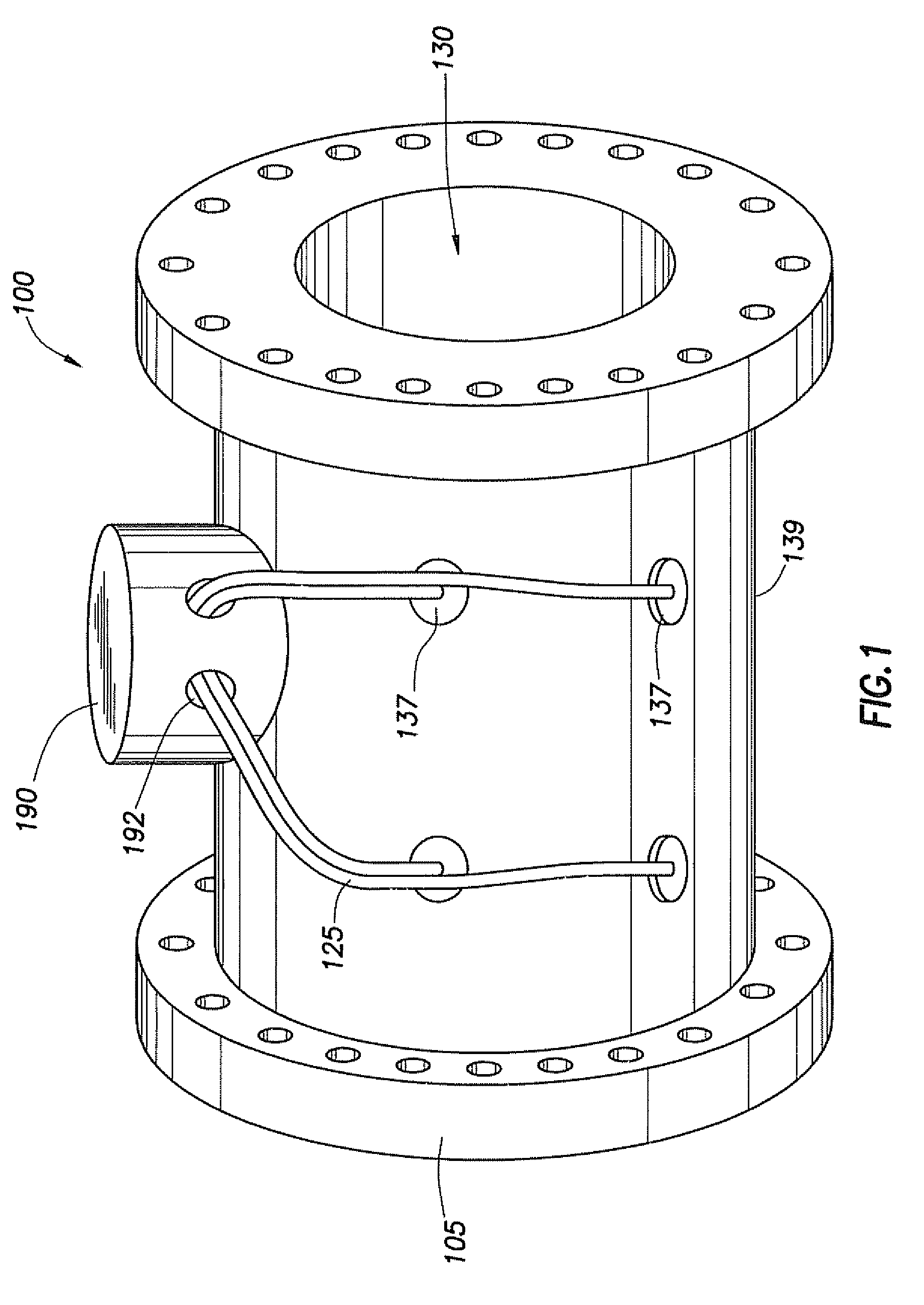
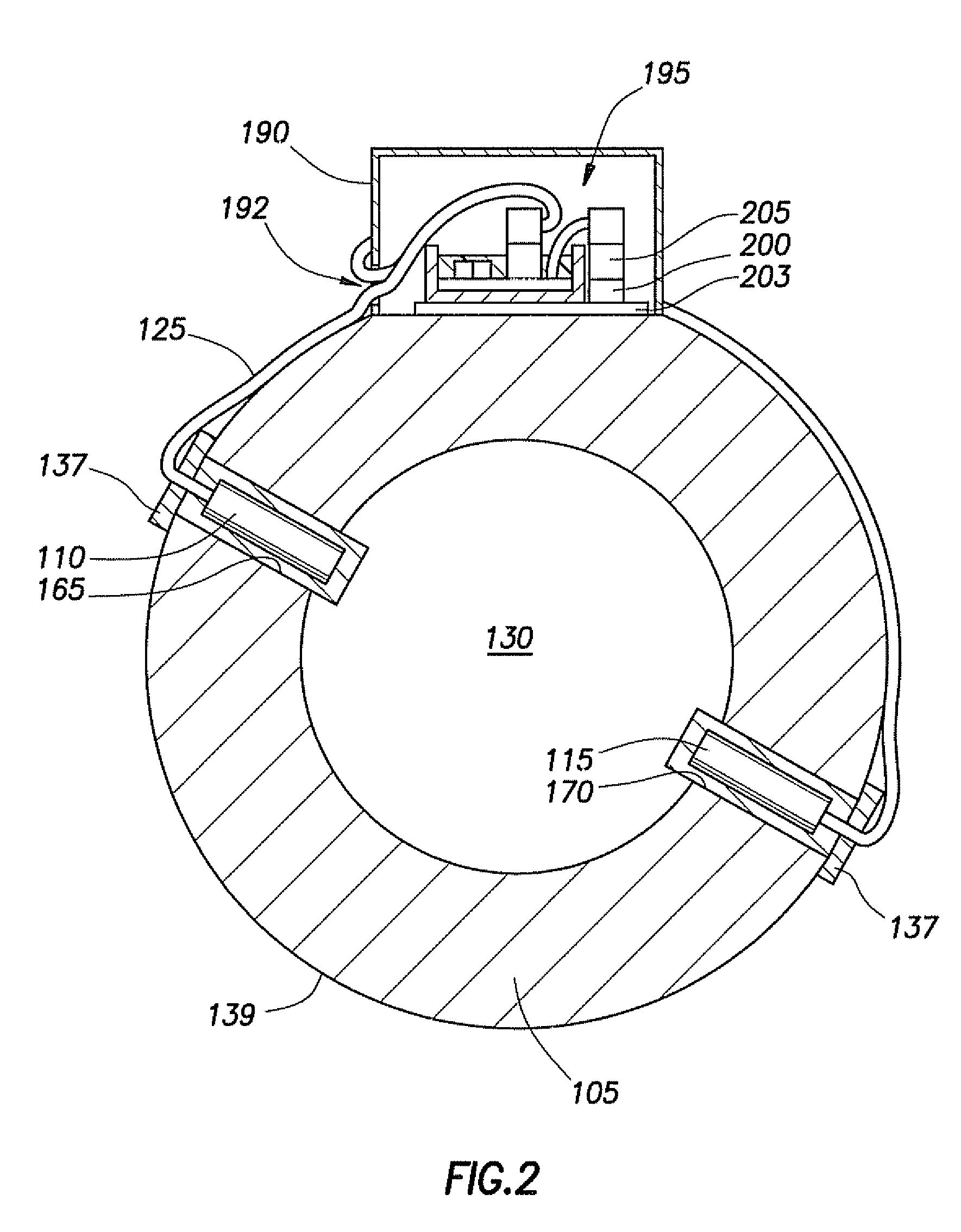
[0029]FIG. 1 is a perspective view of an ultrasonic flow meter with a transformer board in accordance with principles disclosed herein. Ultrasonic flow meter 100 includes spool piece 105 having axial flowbore 130 therethrough and electronics base enclosure 190 coupled to an outer surface 139 of spool piece 105. Spool piece 105 is the housing for ultrasonic flow meter 100 and configured for placement between sections of a pipeline. Fluid flows through bore 130, and that fluid may be corrosive in nature and / or have an extreme temperature. Electronics base enclosure is a cylindrically shaped housing. However, elec...


PUM

PropertyMeasurementUnit
pressureaaaaaaaaaa
impedanceaaaaaaaaaa
ultrasonic flow meteraaaaaaaaaa

Abstract

A transformer board is disclosed. In some embodiments, the transformer board includes a base, a circuit board, a transformer having a first and second winding, a first and a second connector, a ribbon cable and a nonconductive fill material. The base has a recess within which the circuit board is positioned. The transformer is mechanically coupled to the circuit board. The first connector is configured to electrically couple to transducers within a pressure boundary of an ultrasonic flow meter and is electrically coupled to the second winding of the transformer. The ribbon cable is electrically coupled between the first winding of the transformer and the second connector. The nonconductive fill material is contained by the recess and encases the circuit board, the transformer, the coupling of the first connector to the second winding of the transformer, and the coupling of the ribbon cable to the first winding of the transformer.

Description

CROSS-REFERENCE TO RELATED APPLICATIONS[0001]Not applicable.BACKGROUND[0002]1. Field of Art[0003]This disclosure relates to ultrasonic flow meters. More particularly, the disclosure relates to a transformer board that enables positioning of transformers, coupled to transducers located within an ultrasonic flow meter, outside of the pressure boundary of the flow meter.[0004]2. Description of Related Art[0005]After hydrocarbons have been removed from the ground, the fluid stream (such as crude or natural gas) is transported from place to place via pipelines. It is desirable to know with accuracy the amount of fluid flowing in the stream, and particular accuracy is demanded when the fluid is changing hands, or “custody transfer.” Even where custody transfer is not taking place, however, measurement accuracy is desirable.[0006]Ultrasonic flow meters may be used in situations such as custody transfer. An ultrasonic flow meter includes two or more transducers, each contained within a hous...

Claims


Application Information

Patent Timeline
Patent Type & Authority Applications(United States)
IPC IPC(8): H01F27/06G01F1/66
CPCG01F1/662G01F1/667H01R12/59H01R2201/20H01R2201/22H01R9/24
Inventor ALLEN, CHARLES ROBERT
Owner MICRO MOTION INC
Why Eureka
Try Eureka