
Dll circuit and method of controlling the same

a dll circuit and circuit technology, applied in pulse generators, pulse manipulation, pulse techniques, etc., can solve the problems of increased output data access time, long operation time, and easy variation of duty ratio of output clock signals from dll circuits, so as to improve the duty ratio characteristic

Active Publication Date: 2009-07-16
SK HYNIX INC
View PDF7 Cites 3 Cited by
  • Summary
  • Abstract
  • Description
  • Claims
  • Application Information

AI Technical Summary

Benefits of technology

[0008]A DLL circuit that is capable of generating a clock signal having an improved duty ratio characteristic and a method of controlling the same are described herein.

Problems solved by technology

The DLL circuit is also used to resolve the following problem: If an internal clock signal used in a semiconductor integrated circuit is delayed by a clock signal buffer and a transmission line, a phase difference is generated between the internal clock signal and an external clock signal, which results in an increased output data access time.
However, the duty ratio of the output clock signal from the DLL circuit can easily vary due to jitters outside the DLL circuit and irregular delay values of delay elements inside the DLL circuit.
However, a conventional duty cycle correction device included in a conventional DLL circuit occupies a wide area and has a long operation time, or an operational characteristic thereof is deteriorated when operating at low power.

Method used


Image

  • Dll circuit and method of controlling the same
  • Dll circuit and method of controlling the same
  • Dll circuit and method of controlling the same

Examples


Embodiment Construction

.”

BRIEF DESCRIPTION OF THE DRAWINGS

[0013]Features, aspects, and embodiments are described in conjunction with the attached drawings, in which:

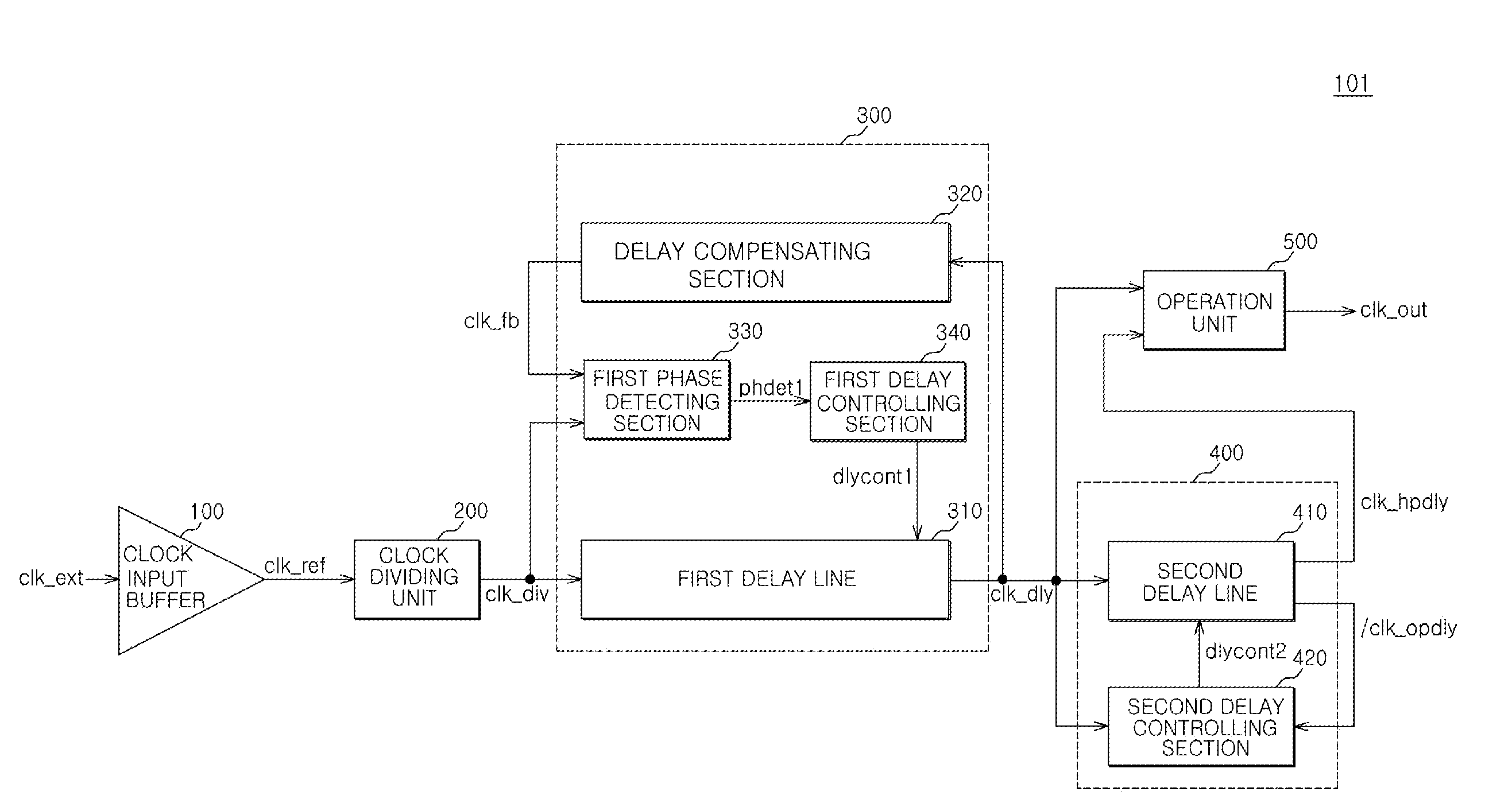
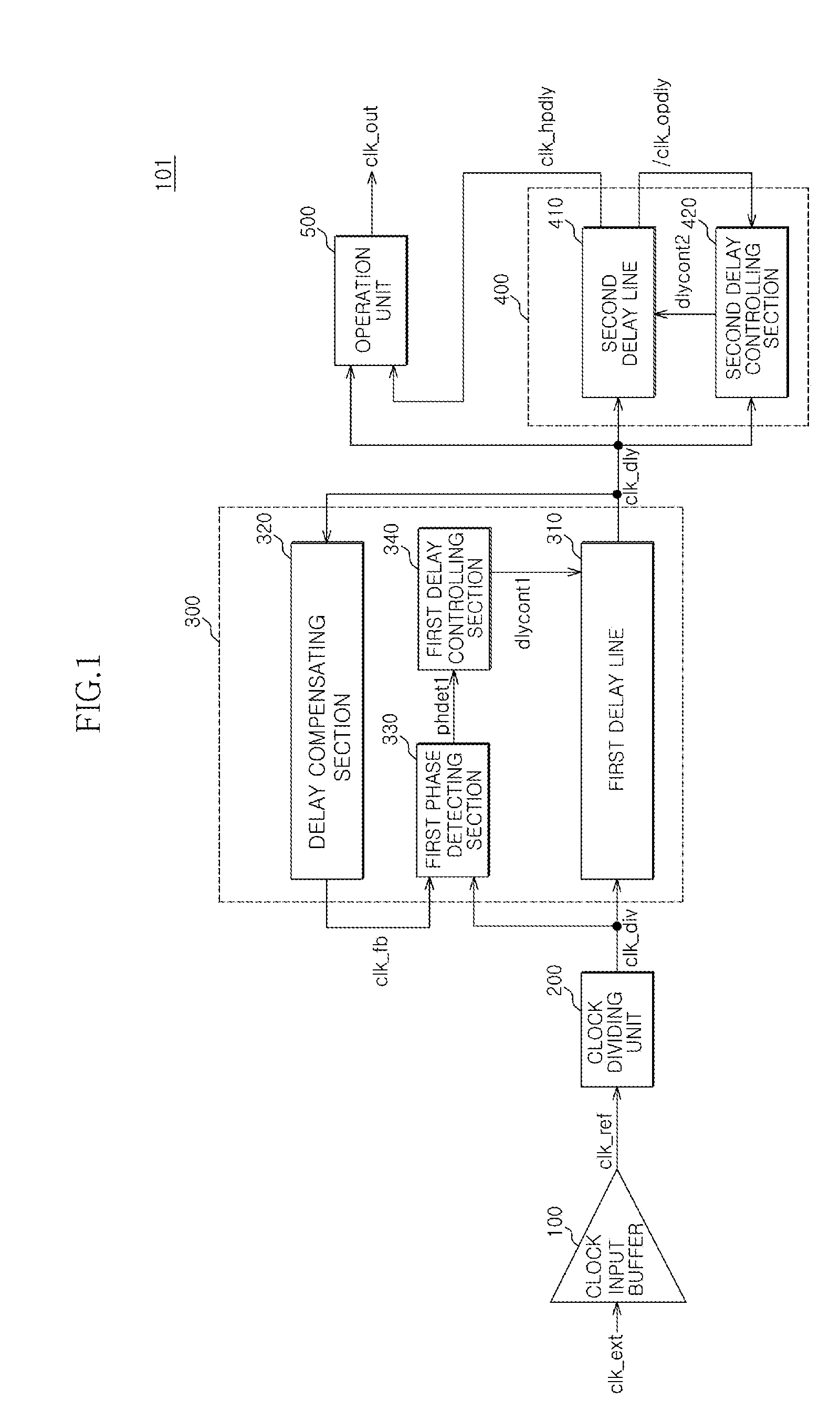
[0014]FIG. 1 is a block diagram illustrating a structure of a DLL circuit according to one embodiment.

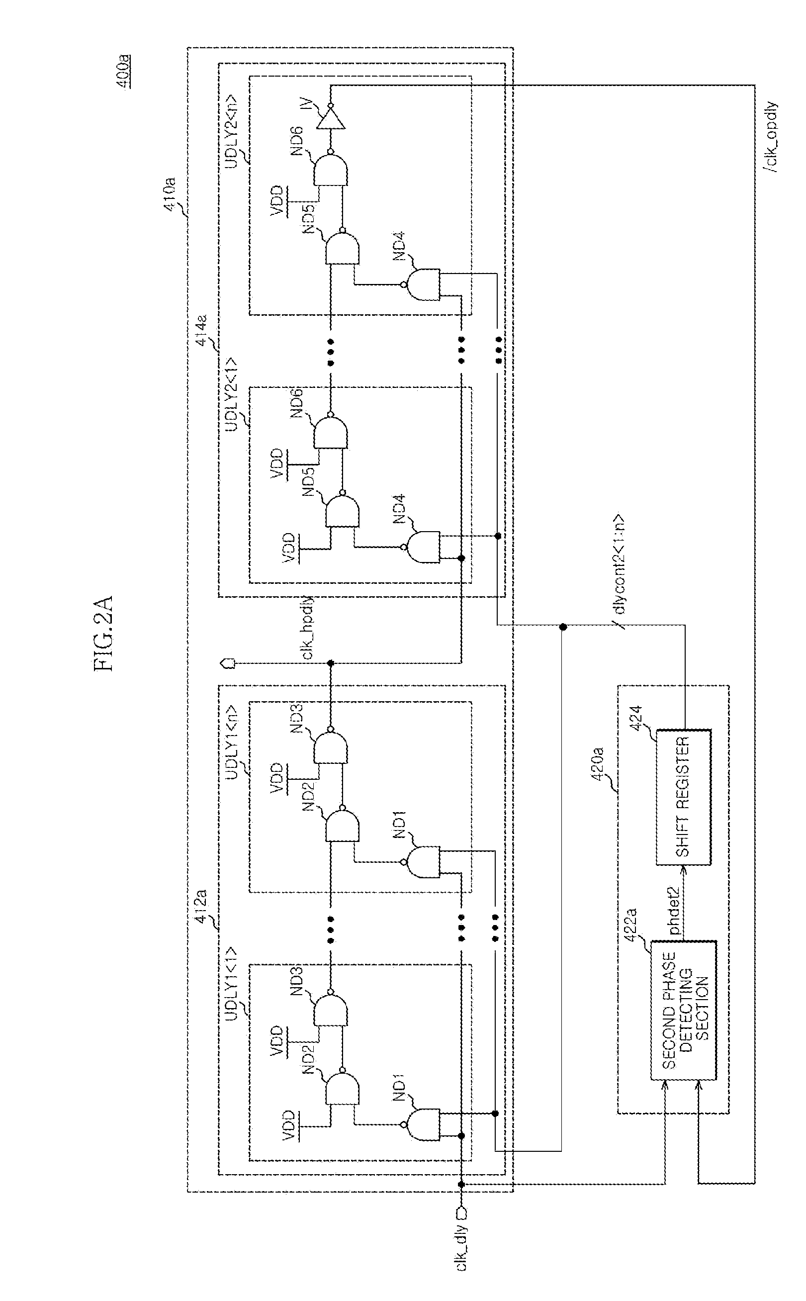
[0015]FIG. 2A is a diagram illustrating a detailed structure of a half period delay unit according to another embodiment and that can be included in the circuit illustrated in FIG. 1.

[0016]FIG. 2B is diagram illustrating a detailed structure of a half period delay unit according to another embodiment and that can be included in the circuit illustrated in FIG. 1.

[0017]FIG. 3 is a timing chart illustrating the operation of a DLL circuit of FIG. 1 in accordance with one embodiment.

DETAILED DESCRIPTION

[0018]FIG. 1 is a block diagram illustrating a structure of a DLL circuit 101 according to one embodiment. Referring to FIG. 1, the DLL circuit 101 can include a clock signal input buffer 100, a clock signal dividing unit 200, a first delay line 310,...


PUM


Abstract

A delay locked loop (DLL) circuit includes a clock signal dividing unit that can divide a reference clock signal by a predetermined division ratio and generate a division clock signal, a feedback loop that can perform a delay locked operation on the division clock signal and generate a delay clock signal, a half period delay unit that can delay the delay clock signal by a half period of the reference clock signal and generate a half period delay clock signal, and an operation unit that can combine the delay clock signal and the half period delay clock signal and generate an output clock signal.

Description

CROSS-REFERENCE TO RELATED PATENT APPLICATION[0001]This application claims the benefit under 35 U.S.C 119(a) of Korean Application No. 10-2008-0004066, filed on Jan. 14, 2008, in the Korean Intellectual Property Office, the disclosure of which is incorporated herein in its entirety by reference as if set forth in full.BACKGROUND[0002]1. Technical Field[0003]The embodiments described herein relate to a delay locked loop (DLL) circuit and a method for controlling the same, and more particularly, to a DLL circuit that can generate an internal clock signal whose phase is more advanced than a phase of an external clock signal and a method for controlling the same.[0004]2. Related Art[0005]In general, a DLL circuit is used to provide an internal clock signal whose phase is more advanced than a phase of a reference clock signal obtained by converting an external clock signal. The DLL circuit is also used to resolve the following problem: If an internal clock signal used in a semiconductor ...

Claims


Application Information

Patent Timeline
Patent Type & Authority Applications(United States)
IPC IPC(8): H03L7/06
CPCH03L7/07H03L7/0814H03L7/0812H03L7/0816H03L7/00H03L7/081
Inventor LEE, HYUN WOOYUN, WON JOO
Owner SK HYNIX INC
Learn More