Printhead maintenance facility with nozzle wiper movable parallel to media feed direction

a technology of nozzle wiper and maintenance facility, which is applied in the field of printers, can solve the problems of difficult cleaning of printheads, easy clogging of nozzles, color mixing,

Inactive Publication Date: 2009-07-16
ZAMTEC +1
View PDF100 Cites 3 Cited by
  • Summary
  • Abstract
  • Description
  • Claims
  • Application Information

AI Technical Summary

Problems solved by technology

The small nozzles clog easily and paper dust or dried ink on the nozzle face (the exterior surface defining the array of nozzle apertures) can cause color mixing between closely spaced nozzles of different color.
However, pagewidth printheads are difficult to wipe.
While pagewidth printers with nozzle face wipers exist, the wiping mec

Method used


Image

  • Printhead maintenance facility with nozzle wiper movable parallel to media feed direction
  • Printhead maintenance facility with nozzle wiper movable parallel to media feed direction
  • Printhead maintenance facility with nozzle wiper movable parallel to media feed direction

Examples


Embodiment Construction

Printer Fluidic System

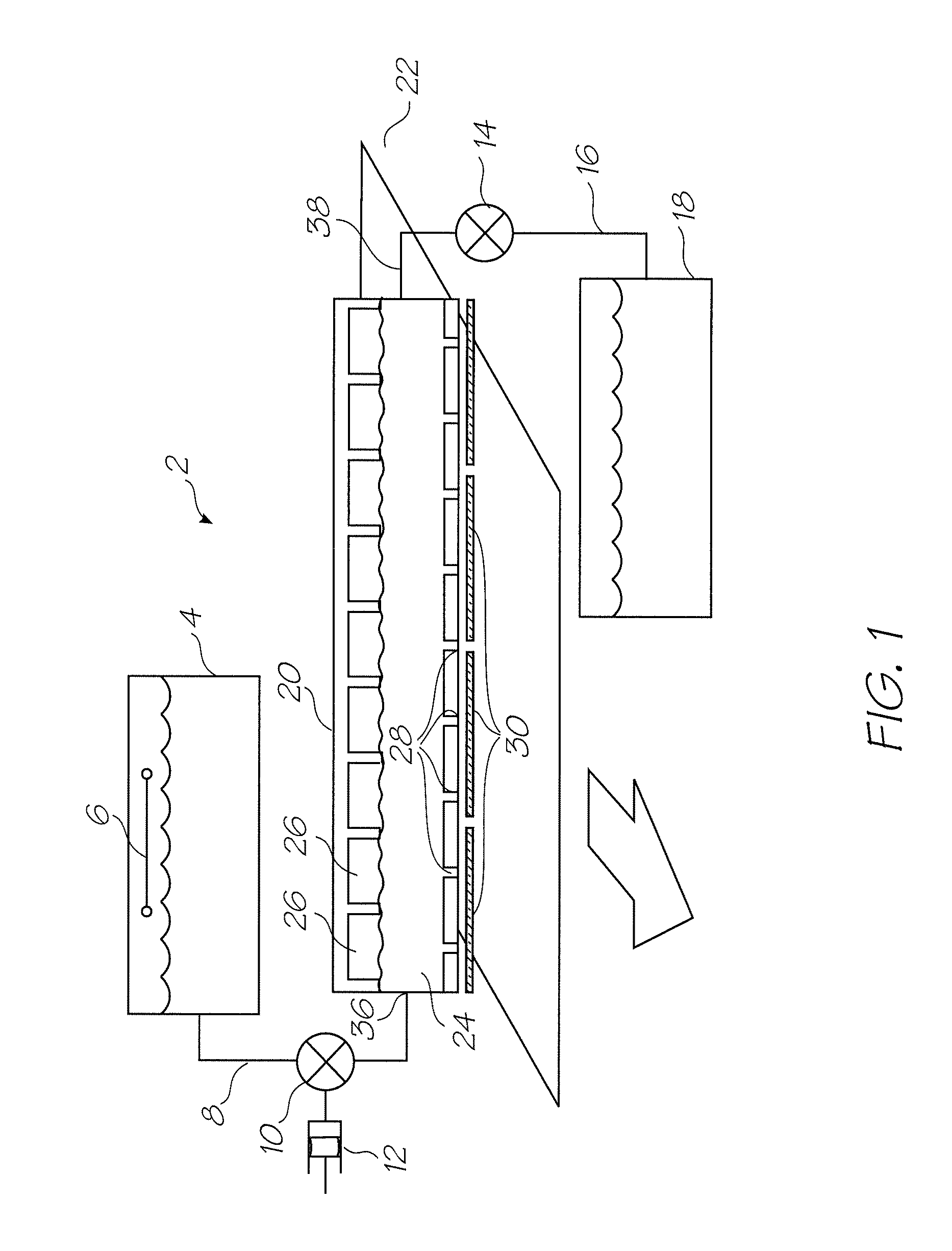
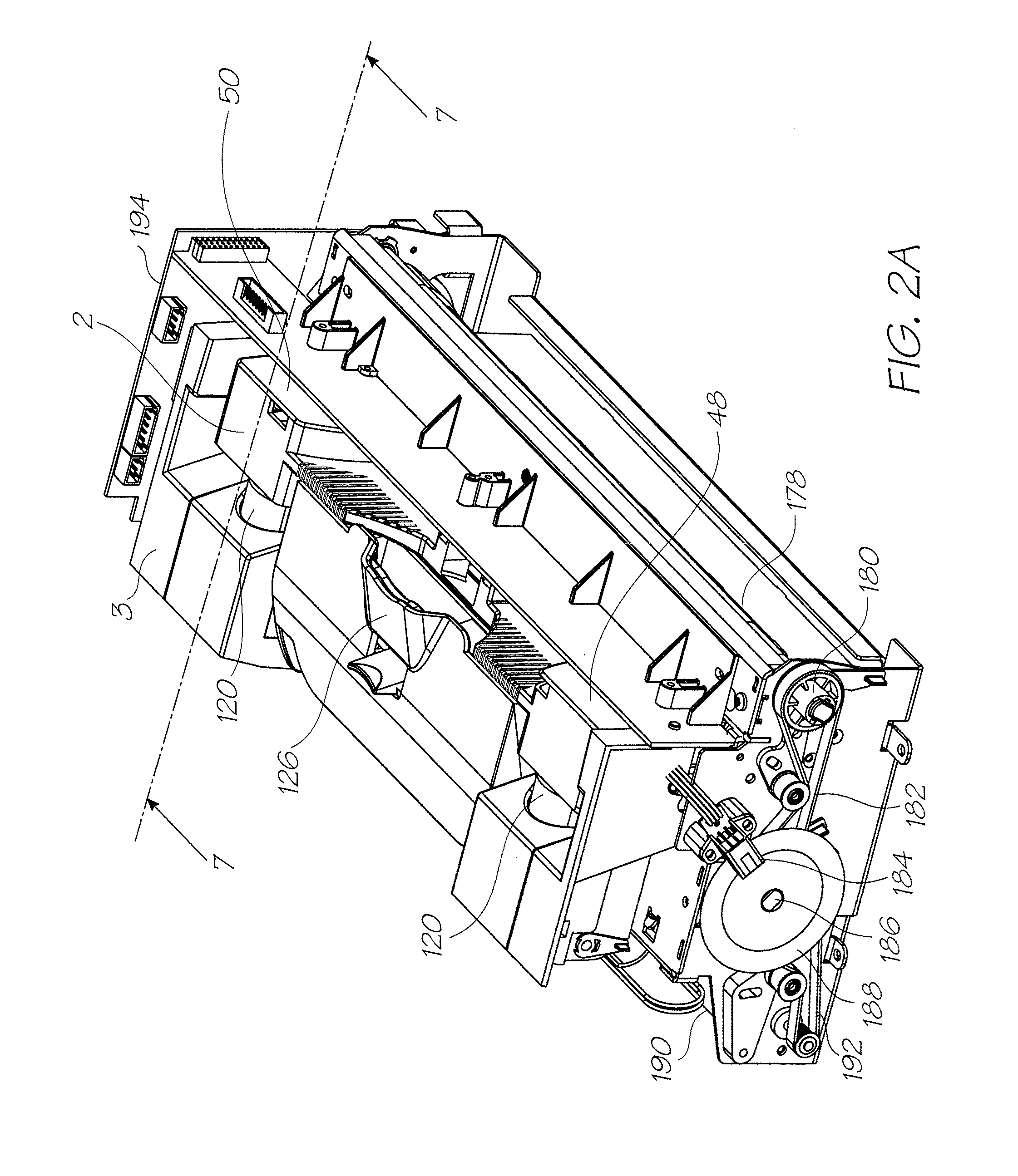
[0068]FIG. 1 is a schematic overview of the fluidic system used by the print engine described in FIGS. 2A and 2B. As previously discussed, the print engine has the key mechanical structures of an inkjet printer. The peripheral structures such as the outer casing, the paperfeed tray, paper collection tray and so on are configured to suit the specific printing requirements of the printer (for example, the photo printer, the network printer or Soho printer). The Applicant's photo printer disclosed in the co-pending application U.S. Ser. No. 11 / 688,863 (Our Docket No. RRE001US) is an example of an inkjet printer using a fluidic system according to FIG. 1. The contents of this disclosure are incorporated herein by reference. The operation of the system and its individual components are described in detail in U.S. Ser. No. 11 / 872,719 (Our Docket No.SBF009US) the contents of which are incorporated herein by reference.

[0069]Briefly, the printer fluidic system has a pri...


PUM


Abstract

A maintenance facility for an inkjet printer having a pagewidth printhead and a media path for feeding sheets of media substrate in a media feed direction. The pagewidth printhead has an elongate array of nozzles extending the printing width of the media substrate and the maintenance facility has a wiper member extending the length of the nozzle array, the wiper member mounted in the printer adjacent the media path and, a maintenance drive for moving the wiper member such that it wipes the array of nozzles in a direction parallel to the media feed direction.

Description

FIELD OF THE INVENTION[0001]The present invention relates to printers and in particular inkjet printers.CO-PENDING APPLICATIONS[0002]The following applications have been filed by the Applicant simultaneously with the present application:RRE012USRRE013USRRE014USRRE015USRRE016USRRE017USRRE019USRRE020USRRE021USRRE022USRRE023USRRE024USRRE025USRRE026USRRE027USRRE028USRRE029USRRE030USRRE031USRRE032USRRE033USRRE034USRRE035USRRE036USRRE037USRRE038USRRE039USRRE040USRRE041USRRE042USRRE043USRRE044USRRE045USRRE046US[0003]The disclosures of these co-pending applications are incorporated herein by reference. The above applications have been identified by their filing docket number, which will be substituted with the corresponding application number, once assigned.CROSS REFERENCES[0004]The following patents or patent applications filed by the applicant or assignee of the present invention are hereby incorporated by cross-reference.6276850652063161589076539180627017764050556628430683513566265296981...

Claims


Application Information

Patent Timeline
IPC IPC(8): B41J2/165
CPCB41J2/16585
Inventor HIBBARD, CHRISTOPHERMACKEY, PAUL IANTSUBONO, MAKOMOABRAHAM, NICHOLAS KENNETHSILVERBROOK, KIA
Owner ZAMTEC
Why Eureka
Try Eureka