Microfluidic separator

a microfluidic separator and microfluidic technology, applied in microstructural devices, machines/engines, borehole/well accessories, etc., can solve the problems of fine emulsions taking months to separate, conventional separation techniques often take a long time,

Inactive Publication Date: 2009-07-23
SCHLUMBERGER TECH CORP
View PDF6 Cites 33 Cited by
  • Summary
  • Abstract
  • Description
  • Claims
  • Application Information

AI Technical Summary

Benefits of technology

[0010]According to some aspects, the membrane may be a water-repellant, oil-permeable membrane; an oil-repellent, water-permeable membrane; an oil-and-water-repellent gas permeable membrane, or other membrane. A liquid of interest from the multiphase mixture may flow through the membrane at a flow rate at least one-to-two orders of magnitude lower than a flow rate of the multiphase mixture passing by the membrane. The separation may comprise passing a liquid of interest from the multiphase mixture through the membrane and preventing the membrane from fouling without back-flushing. After separation, the fluid of interest may pass into an H-fractal fluid channel configuration.

Problems solved by technology

One drawback of conventional separation techniques is the time it takes to perform them.
Conventional separation techniques often take a long time, depending on the particular composition of the fluid.
For example, a fine emulsion may take months to separate by gravity, although a simple mixture may take only a few minutes.
Another drawback of conventional separation techniques is poor separation performance.
Conventional separation techniques usually do not perform a complete separation.
However, bringing sample fluids to the surface, transporting them to a laboratory, and separating the phase mixtures is time consuming, cost inefficient and provides only post-factum information.

Method used


Image

  • Microfluidic separator
  • Microfluidic separator
  • Microfluidic separator

Examples


Embodiment Construction

[0027]Illustrative embodiments and aspects of the invention are described below. It will of course be appreciated that in the development of any such actual embodiment, numerous implementation-specific decisions must be made to achieve the developers' specific goals, such as compliance with system-related and business-related constraints that will vary from one implementation to another. Moreover, it will be appreciated that such a development effort might be complex and time-consuming but would nevertheless be a routine undertaking for those of ordinary skill in the art having the benefit of this disclosure.

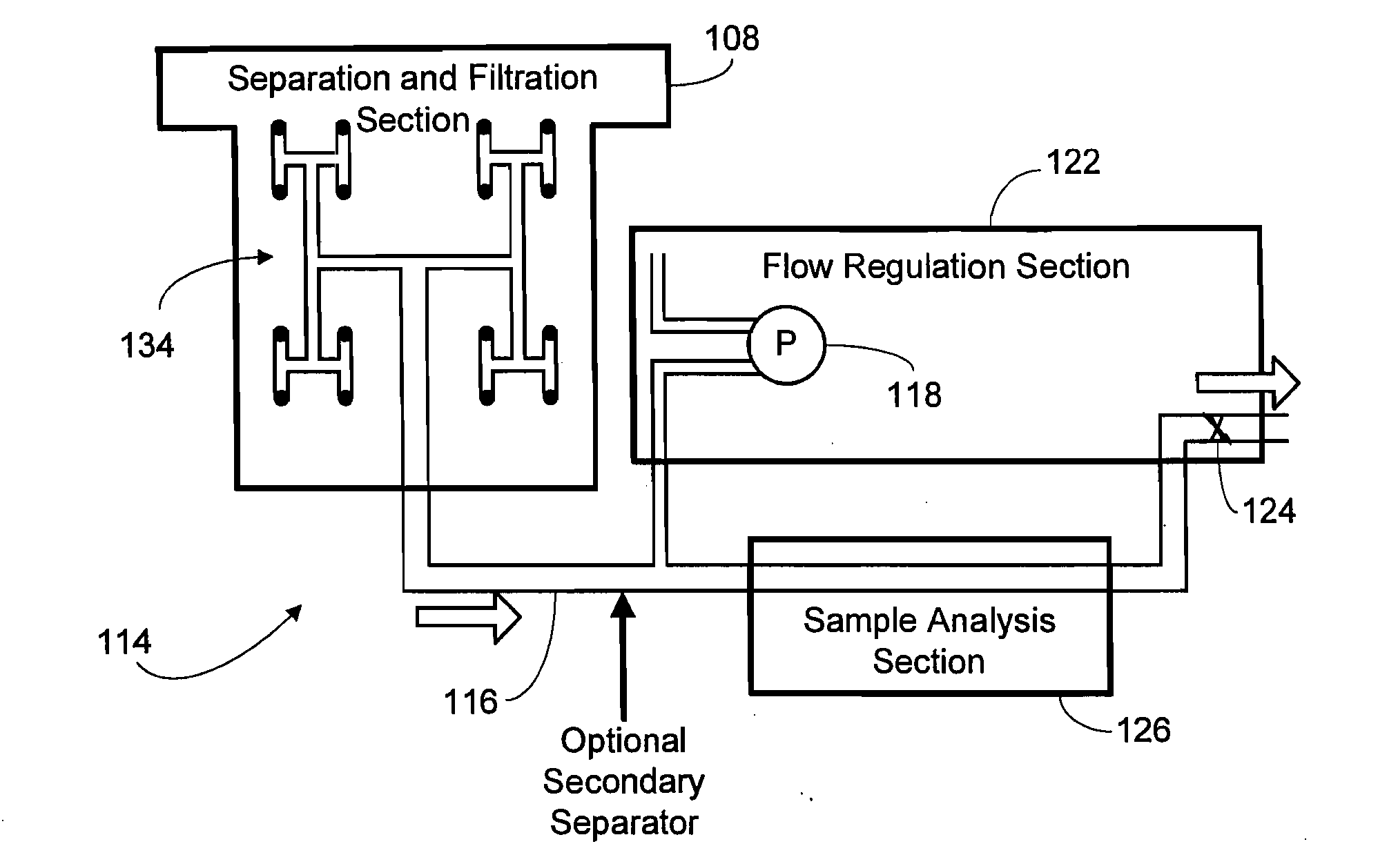
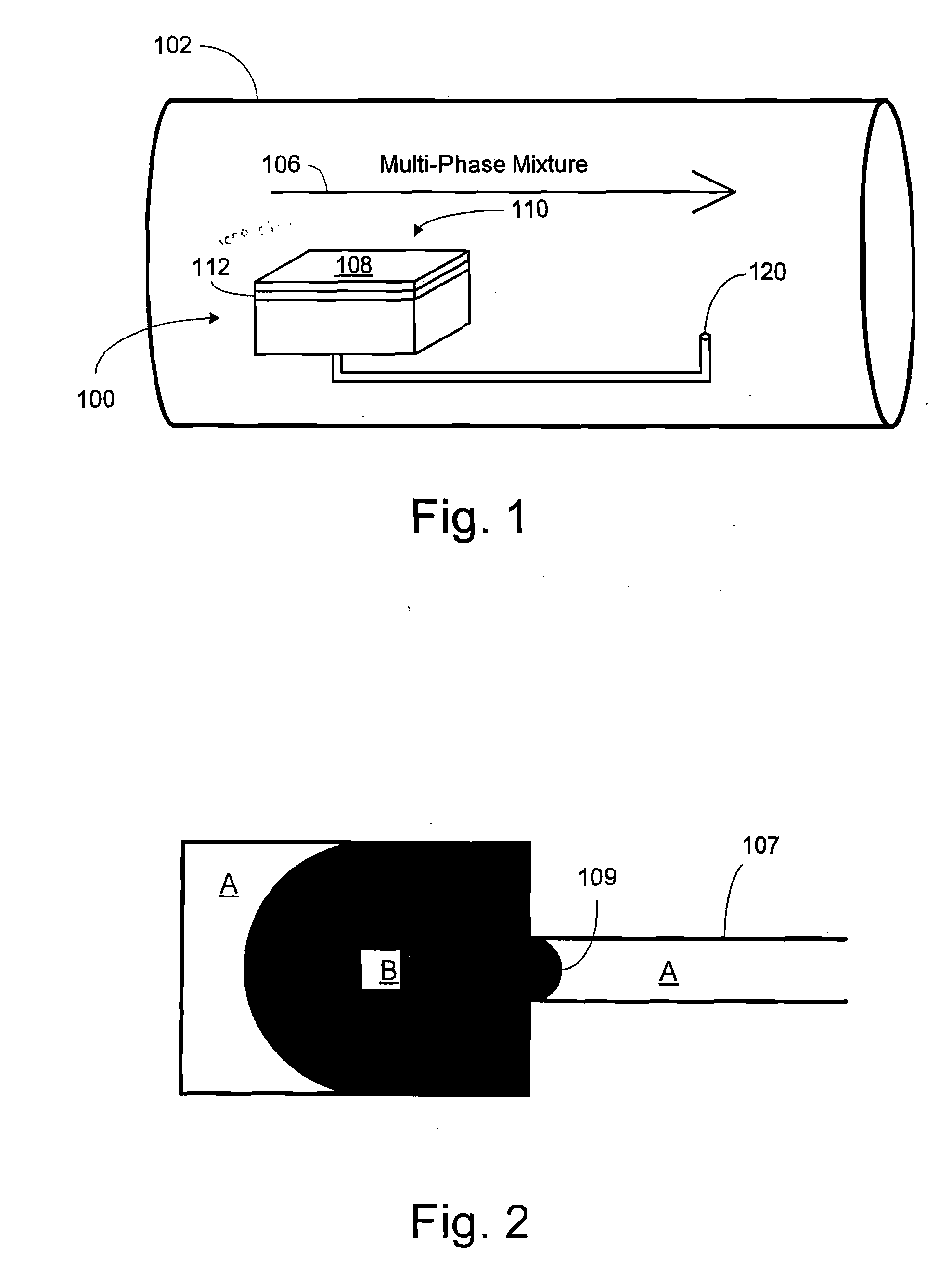
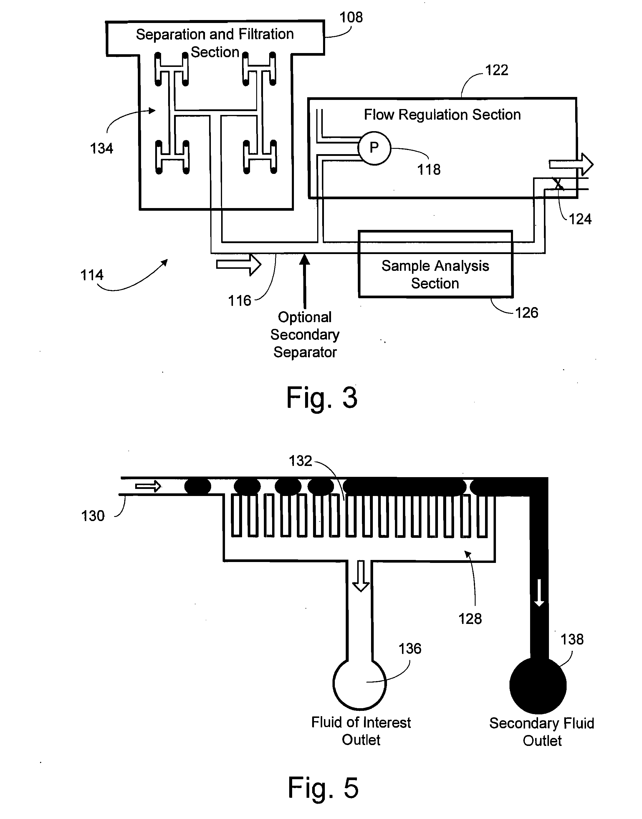
[0028]The present invention contemplates methods and apparatus for separating multiphase mixtures including liquid-gas mixtures, liquid-liquid mixtures, and emulsions, especially in microfluidic devices. As mentioned in the background, in many applications, including oil well evaluation and aquifer management, fluid samples must be separated and analyzed. The principles describe...


PUM

PropertyMeasurementUnit
pressureaaaaaaaaaa
oil-permeableaaaaaaaaaa
water-permeableaaaaaaaaaa

Abstract

The present invention provides methods and apparatus for separating and / or analyzing fluids of interest. According to principles of the present invention, fluid analysis is accomplished with microfluidic devices and may be reported in real-time or near real-time in a subterranean environment. In addition or alternative to oilfield applications, the principles of the present invention contemplate separation in a laboratory or other environment for biological sample separation and analytical chemistry applications. The present invention is capable of separating liquid-liquid mixtures or emulsions in a microfluidic device without fouling.

Description

[0001]This patent application claims priority from U.S. patent application Ser. No. 10 / 885,471 filed Jul. 6, 2004, incorporated by reference herein in its entirety.FIELD OF THE INVENTION[0002]The present invention relates to chemical analysis and, more particularly, to the separation of fluids in microfluidic systems.BACKGROUND[0003]The ability to reliably separate a fluid of interest can be very beneficial for oilfield, medical, biological, and analytical chemistry applications. Fluids of interest may include water, oil, gas, or other fluids. Separating fluids of interest enables specific measurements to be performed on the particular fluid. For example, pH and various ion concentrations may be measured if the fluid of interest is water. For oil, near-infrared absorption spectroscopy may be performed to detect various light-weight hydrocarbons, and other types of chromatography may be used to detect detailed chemical composition.[0004]However, in order to perform accurate measureme...

Claims


Application Information

Patent Timeline
Patent Type & Authority Applications(United States)
IPC IPC(8): B01D61/00B01D19/00B01D61/32E21B47/00B01D61/18B01D67/00B01L3/00B01L99/00E21B43/38E21B47/10E21B49/08E21B49/10G01N1/34G01N1/40G01N33/28
CPCB01D17/085Y10T436/25375B01D61/18B01D67/0062B01L3/502753B01L2200/0673B01L2300/0681B01L2300/0864B01L2300/161B01L2400/0487E21B43/38E21B47/10E21B49/081E21B49/10G01N1/4005G01N33/28G01N2001/4016B01D19/0031B01D63/00B01D63/08B81B1/00G01N1/40
Inventor SALAMITOU, PHILIPPEWONG, JOYCERAGHURAMAN, BHAVANISHAH, JAGDISHVAN HAL, RONALD E. G.SCHROEDER, ROBERT J.RENE TABELING, PATRICK JEAN
Owner SCHLUMBERGER TECH CORP
Why Eureka
Try Eureka