Acoustic exciter and speaker using it

a technology of acoustic exciters and speakers, applied in loudspeakers, magnets, propulsion systems, etc., can solve the problems of low operating efficiency, many conventional acoustic exciters, and the decrease of vibration in other frequency regions, so as to reduce the attenuation of vibration and broaden the sound reproduction range

Active Publication Date: 2009-07-23
PANASONIC CORP
View PDF20 Cites 23 Cited by
  • Summary
  • Abstract
  • Description
  • Claims
  • Application Information

AI Technical Summary

Benefits of technology

[0011]An acoustic exciter in the present invention includes a magnetic circuit, a suspension connected to the magnetic circuit, a frame coupled to the suspension, a voice coil disposed in the magnetic gap of magnetic circuit, and a vibrator coupled to the voice coil. The vibrator and the frame are so coupled via an elastic body as to be able to move ups and downs relative to each other. The above-described acoustic exciter provides a broader sound reproduction range and a reduced attenuation of vibration.

Problems solved by technology

Therefore, although it provides a substantial vibration by series resonance at the lowest resonance frequency F0, the vibration decreases in other frequency region because energy is consumed by the load of the entire vibration mass.
As the result, many of the conventional acoustic exciters demonstrate low operating efficiency, narrow sound reproduction range.
There are problems in this sector still left to be solved; viz. the sound pressure and the quality of reproduced sounds.

Method used


Image

  • Acoustic exciter and speaker using it
  • Acoustic exciter and speaker using it
  • Acoustic exciter and speaker using it

Examples


first exemplary embodiment

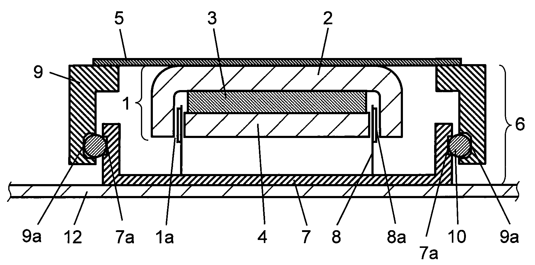
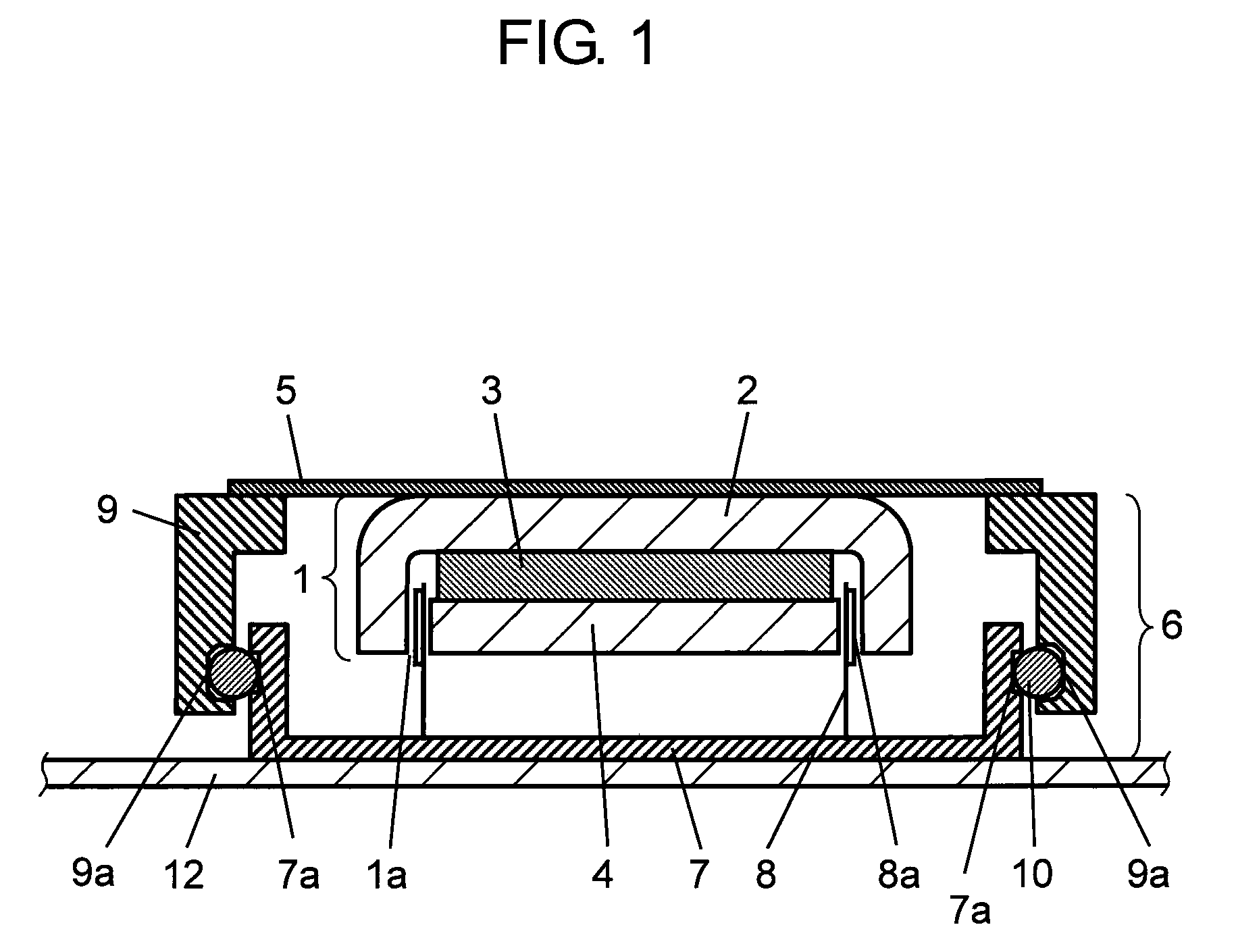
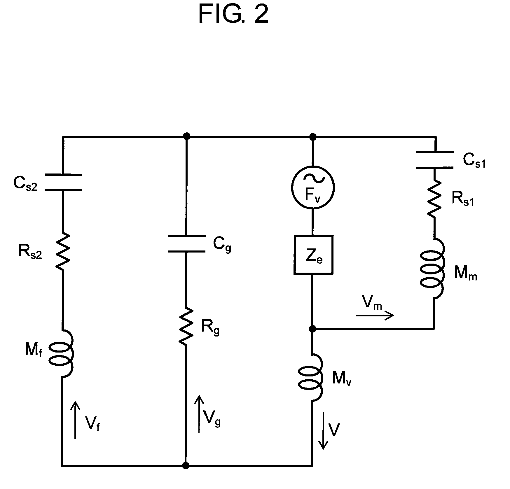
[0056]An acoustic exciter is described in accordance with a first exemplary embodiment of the present invention, with reference to the drawings. FIG. 1 shows a cross sectional side view of an acoustic exciter in the present embodiment. FIG. 2 is an equivalent circuit diagram representing the mechanical system of the exciter.

[0057]Reference is made to FIG. 1. Frame 9 has an open part at both ends. Magnetic circuit 1 is provided by stacking and gluing magnet 3 and plate 4 on yoke 2. Magnetic circuit 1 is so supported by suspension 5, which is connected to one of the open ends of frame, as to be able to move ups and downs freely within the inside of frame 9. Voice coil 8 is disposed at its one end in magnetic gap la of magnetic circuit 1, while the other end is connected glued to vibrator 7 of a bottomed cylindrical shape disposed at the other end of frame 9. Thus the acoustic exciter is formed of frame 9, magnetic circuit 1, voice coil 8, and vibrator 7 which is connected to voice coi...

second exemplary embodiment

[0071]A second exemplary embodiment of the present invention is described referring to FIG. 4 through FIG. 7C. FIG. 4 shows a cross sectional side view of an acoustic exciter in accordance with the present embodiment. FIG. 5 is a cross sectional side view used to describe the mounting of acoustic exciter in the present embodiment with a bracket, which bracket being the key element of a vibration staff of a sound reproduction apparatus formed in combination with the acoustic exciter. FIG. 6A shows a bottom view of frame, which being a key part of the present embodiment, FIG. 6B is the side view. FIG. 7A shows the bracket as viewed from the above, which bracket being a key part of the present embodiment, FIG. 7B is the side view. FIG. 7C is other side view, as seen from a direction revolved by a 90 degree from that of FIG. 7B.

[0072]The main feature with an acoustic exciter in the present embodiment is in a structure provided to make connection of the acoustic exciter and vibration sta...


PUM


Abstract

An acoustic exciter comprises a suspension made of an elastic material, which is coupled to the opening part of a frame, and a vibrator to which a voice coil disposed in the magnetic gap of a magnetic circuit connected to the suspension is coupled. An elastic body is so disposed between the frame and the vibrator as to be pressed against the frame and the vibrator. Thereby, the exciting efficiency of the vibrator can be increased, and the performance and tone quality of the acoustic exciter can be improved.

Description

TECHNICAL FIELD[0001]The present invention relates to an acoustic exciter which vibrates a panel staff, such as an automobile cabin interior material, a house interior panel, etc., for reproducing sounds. A speaker which includes the acoustic exciter is also disclosed in the present invention.BACKGROUND ART[0002]An acoustic exciter is made by combining a magnetic circuit and a vibrator with a suspension having a spring property. Vibration is generated as the result of transaction between the magnetic circuit and the vibrator attracting / repelling to each other. The vibration is conducted to a vibration staff on which the acoustic exciter is mounted. A conventional acoustic exciter is described below referring to FIG. 8 which shows a cross sectional side view of acoustic exciter and FIG. 9 which shows an equivalent circuit diagram representing its mechanical system.[0003]As shown in FIG. 8, a conventional acoustic exciter is formed of magnetic circuit 221 and vibrator 226. Magnetic ci...

Claims


Application Information

Patent Timeline
Patent Type & Authority Applications(United States)
IPC IPC(8): H02K41/035H02K1/34
CPCH04R9/066H04R2499/13H04R2440/05H04R2400/07
Inventor YAMAGISHI, KIYOSHI
Owner PANASONIC CORP
Why Eureka
Try Eureka