Display device

Inactive Publication Date: 2009-07-23
SHARP KK
View PDF1 Cites 50 Cited by
  • Summary
  • Abstract
  • Description
  • Claims
  • Application Information

AI Technical Summary

Benefits of technology

[0021]According to various preferred embodiments of the present invention, there is provided a display device in which detachment of dr

Problems solved by technology

On the other hand, if the manner of mounting the driving elements is changed in order to suppress detachment of the driving elements from the insulative substrate, the design of substrate lines which are electrical

Method used


Image

  • Display device
  • Display device
  • Display device

Examples


Example

[0032]Hereinafter, preferred embodiments of a display device according to the present invention will be described with reference to the drawings. Herein, a liquid crystal display device will be illustrated as an example of a display device.

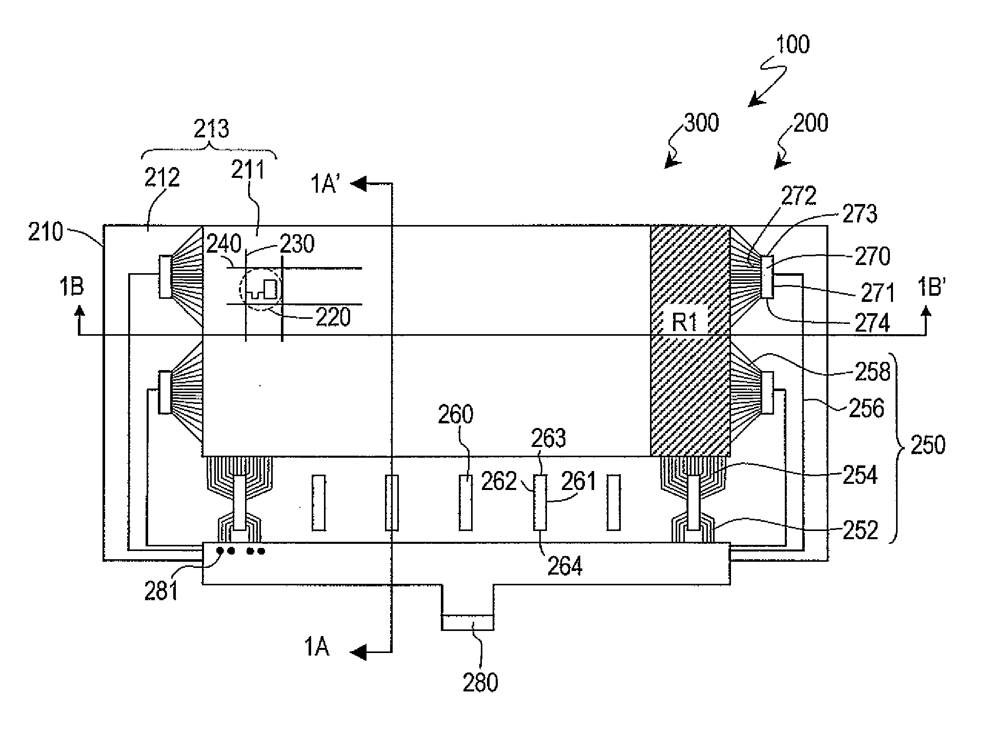
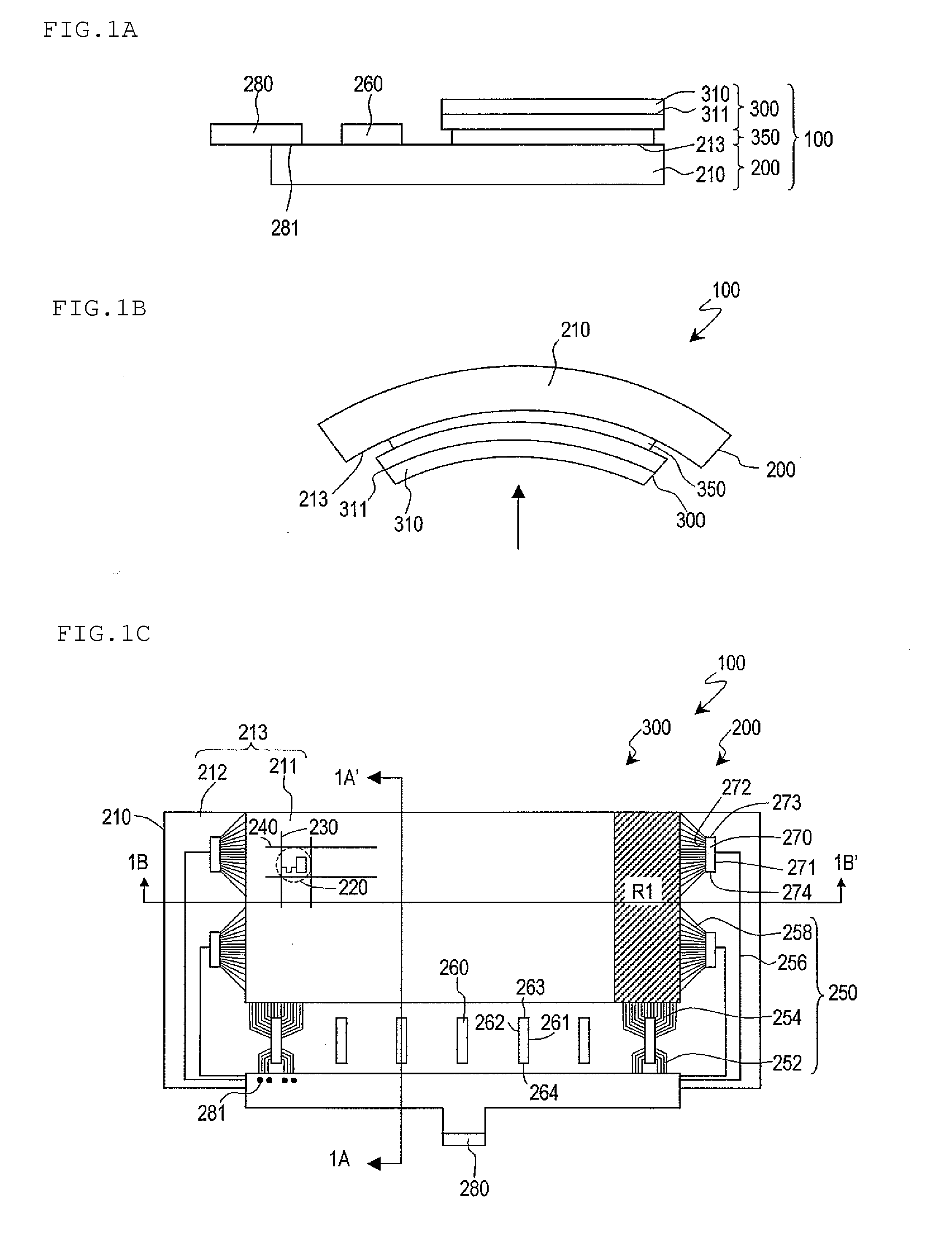
[0033]As shown in FIG. 1A, the display device 100 of the present preferred embodiment includes an active matrix substrate 200, a counter substrate 300, and a display medium layer 350 interposed between the active matrix substrate 200 and the counter substrate 300. As shown in FIG. 1B, the display device 100 of the present preferred embodiment has a curved shape. Herein, the display device 100 is a liquid crystal display device, and the display medium layer 350 is a liquid crystal layer. In this case, an image is displayed when each pixel modulates the light which is emitted from a backlight (not shown).

[0034]FIG. 1C shows a schematic construction when the display device 100 is viewed from the normal direction of the display surface. The active mat...


PUM


Abstract

A display device includes a curved insulative substrate. A substrate line includes first input substrate lines electrically connected to first driving elements and first output substrate lines electrically connected to first lines and the first driving elements. The first output substrate lines are provided so as to be closer to the displaying region than are the first input substrate lines. Each first driving element has a rectangular shape with two longer sides and two shorter sides, the first driving element being mounted so that the longer sides are parallel or substantially parallel to the direction in which the first lines extend.

Description

BACKGROUND OF THE INVENTION[0001]1. Field of the Invention[0002]The present invention relates to a display device, and more particularly to a display device having a curved shape.[0003]2. Description of the Related Art[0004]Generic display devices have substantially planar or rectangular solid shapes. However, in a display device having such a shape, external light in the surroundings may be reflected by an insulative substrate (e.g., a glass substrate), so that the surrounding landscapes may appear as reflection glares overlaid on a video on the display device, possibly causing a misperception of the video. Therefore, adopting a curved shape for the display device is known to suppress reflection glares. In a display device of a curved shape, the insulative substrate is curved in a predetermined shape (see, for example, Japanese Laid-Open Patent Publication No. 11-38395).[0005]Generally speaking, an active matrix substrate that is used for a display device such as a liquid crystal d...

Claims


Application Information

Patent Timeline
IPC IPC(8): G02F1/1345G02F1/1333
CPCB60R11/0235B60R13/10G02F1/13454G02F1/13452G02F1/133305
Inventor TANAKA, SHINYAIMAI, HAJIMETSUKAMURA, CHIKANORIKATAOKA, YOSHIHARU
Owner SHARP KK
Why Eureka
Try Eureka