Wear-preventive air-charger piston structure

a technology of air-charger and piston ring, which is applied in the direction of positive displacement liquid engine, piston pump, liquid fuel engine, etc., can solve the problems ineffective position of teflon powder, and defective piston ring mechanism of the piston mechanism of the air-charger, so as to achieve effective prevention of detachment and breaking of the piston ring at high temperature

Active Publication Date: 2022-04-12
DONGGUAN HESHENG ELECTRICAL & MECHANICAL CO LTD
View PDF2 Cites 0 Cited by
  • Summary
  • Abstract
  • Description
  • Claims
  • Application Information

AI Technical Summary

Benefits of technology

[0006]The present invention provides a wear-preventive air-charger piston structure. The piston structure comprises a piston rod, a piston ring, and a top cover. The piston rod has a top that is formed with a piston top seat. The piston ring is disposed on the piston top seat. The piston ring has a top that is covered with a top cover. A surface of the top cover is provided with an airtight plate mounted thereto. The top cover and the piston top seat are securely fixed together to complete assembly of the piston structure. The piston structure further comprises at least one buffering element. The buffering element is arranged between the piston top seat of the piston rod and the piston ring. The buffering element has an outside diameter that is smaller than an outside diameter of the piston ring, in order to prevent the buffering element from generating contact abrasion with an inside surface of a cylinder.
[0007]The efficacy of the present invention is that at least one buffering element is arranged between the piston top seat of the piston rod and the piston ring, and the buffering element has the characteristics of elastic restoration and resistance to compression and high temperature. When the piston ring is in an inclined oscillating condition and at a high position of an oscillation side, the buffering element may function to absorb (buffer) the stress applied to the piston ring at the high position of the oscillation side to effectively prevent detachment and breaking of the piston ring resulting from stress concentration at a contact point of the piston ring with the inside surface of the cylinder at the high position of the oscillation side.

Problems solved by technology

However, it has been long a trouble to the manufactures that a piston ring mechanism of a piston mechanism of an air charger is defective in that, as the most important drawback among others, when the piston ring moves up and down in a cylinder, a stress resulting from pulling and driving may cause detachment and breaking of the piston ring.
However, it has been found that in an operation (or test) of a piston ring with Teflon powder applied thereon, the Teflon powder shows an ineffective position, which is generally at a high position at the oscillation side that a crankshaft drives a pull rod assembly (for example, with the cylinder head removed and the crankshaft and the pull bar assembly left on a spindle of a motor for operation, when dynamic balance is reached, the pull bar assembly forms an angle relative to a vertical line and is undergoing an up-and-down reciprocal motion in an inclined condition; and as analysis from the view angle position of the piston ring, since the crankshaft drives the pull bar assembly in an inclined condition, the oscillation side of the piston ring at one side is at the highest position for relative position thereof).
The high position of the oscillation side of the piston ring would make the piston ring contacting an inside surface of the cylinder, so as to be in a worse condition of stress concentration, leading to contact point of the piston ring with the inside surface of the cylinder at the high position of the oscillation side would easily cause detachment and breaking of the piston ring due to stress of stretching.

Method used


Image

  • Wear-preventive air-charger piston structure
  • Wear-preventive air-charger piston structure
  • Wear-preventive air-charger piston structure

Examples


Embodiment Construction

[0013]For better understanding of the features and advantages of the present invention and to more clearly demonstrate the efficacy that can be achieved by the present invention, a detail description of the features and the advantages of the present invention will be provided below, with reference to the attached drawings. The aspect of the present invention will be expounded with reference to embodiment provided below, which, however, are not intended to impose constrains to the scope of the present invention in any respect.

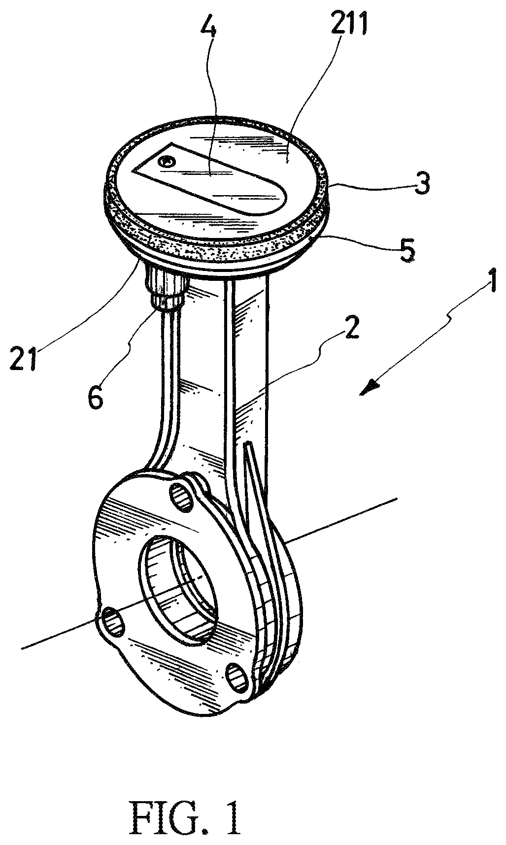
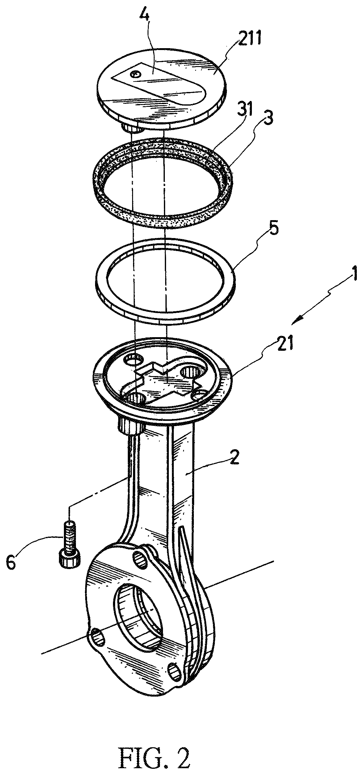
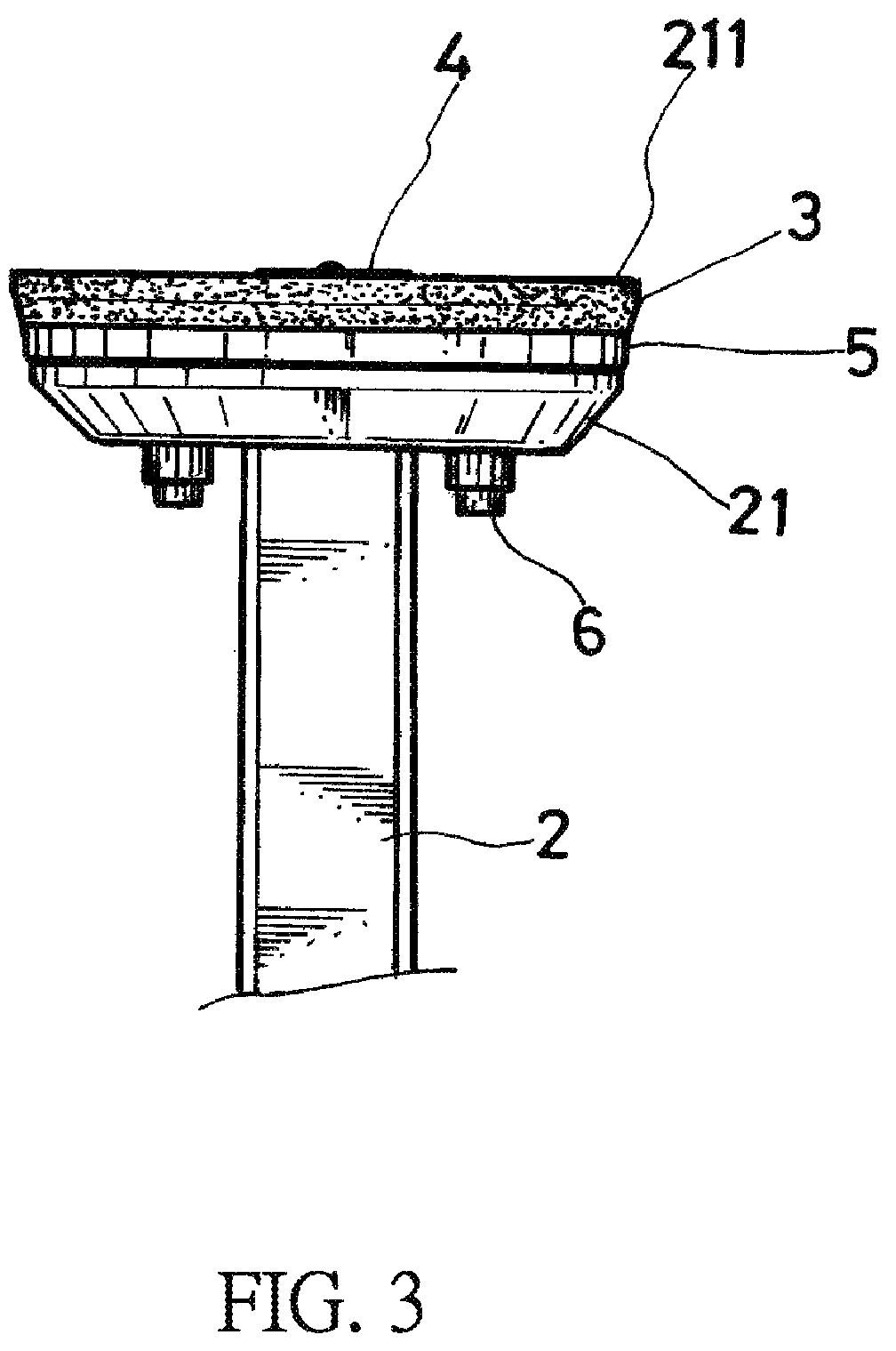
[0014]Referring first to FIGS. 1, 2, 3, and 4, the present invention discloses a wear-preventive air-charger piston structure. The piston structure 1 comprises a piston rod 2, a piston ring 3, and a top cover 211.

[0015]The piston rod 2 has a top that is formed with a piston top seat 21, and the piston top seat 21 has a bottom that is provided with features including a plurality of air ingress holes and a plurality of locking holes. Such features are not novel pa...


PUM


Abstract

A wear-preventive air-charger piston structure is provided. The piston rod has a top forming a piston top seat on which a piston ring is disposed. The piston ring is covered with a top cover that is combined with the piston top seat. The top cover is provided with an airtight plate mounted thereto to form a complete piston structure. A buffering element is arranged between the piston top seat and the piston ring. The buffering element has an outside diameter smaller than the piston ring, so that when the piston ring, which is driven by a crankshaft to do an up-and-down movement, is put in an inclined oscillating condition and at a high position of an oscillation side, the buffering element functions to absorb the stress acting on the piston ring at the high position of the oscillation side to effectively prevent detachment and breaking of the piston ring.

Description

TECHNICAL FIELD OF THE INVENTION[0001]The present invention relates to a wear-preventive air-charger piston structure, and more particularly to at least one buffering element being arranged between a piston top seat of a piston rod and a piston ring, wherein the buffering element has the characteristics of elastic restoration or springing back and the buffering element has an outside diameter smaller than an outside diameter of the piston ring to prevent contact abrading of the buffering element with an inside surface of a cylinder, so that when the piston ring, as being driven by a crankshaft, is put in an inclined oscillating condition and at a high position of an oscillation side, the buffering element functions to absorb (buffer) the stress applied to the piston ring at the high position of the oscillation side to effectively prevent detachment and breaking of the piston ring resulting from over concentration of stress at a contact point of the piston ring with the inside surfac...

Claims


Application Information

Patent Timeline
Patent Type & Authority Patents(United States)
IPC IPC(8): F16J1/12F16J1/00F04B39/00F16J1/02F04B53/14
CPCF16J1/005F04B39/0005F04B53/14F16J1/02F16J1/12F04B35/04F04B35/01F16J1/008
Inventor CHEN, CHI-WEN
Owner DONGGUAN HESHENG ELECTRICAL & MECHANICAL CO LTD
Why Eureka
Try Eureka