Light-based touch screen

a touch screen and light-based technology, applied in computing, instruments, electric digital data processing, etc., can solve the problems of inability to accurately interpret inputs, limited touch screen types, and limited inputs of users, so as to reduce the number of io connectors required and reduce the cost of materials for the touch screen

Active Publication Date: 2009-07-30
NEONODE
View PDF99 Cites 232 Cited by
  • Summary
  • Abstract
  • Description
  • Claims
  • Application Information

AI Technical Summary

Benefits of technology

[0014]In some embodiments of the present invention, the LEDs are connected as a matrix to LED row drivers that select rows and LED column drivers that select columns. As such, a designated LED is activated by appropriately setting its corresponding row and

Problems solved by technology

When space is at a premium, such as with small handheld electronic devices, conventional touch screens are limited to only a few user inputs.
Moreover, these inputs are not accurately interpreted when the user does not use a stylus.
Conventional touch screens are also limited as to the types of user inputs that they can recognize.
For

Method used


Image

  • Light-based touch screen
  • Light-based touch screen
  • Light-based touch screen

Examples


Embodiment Construction

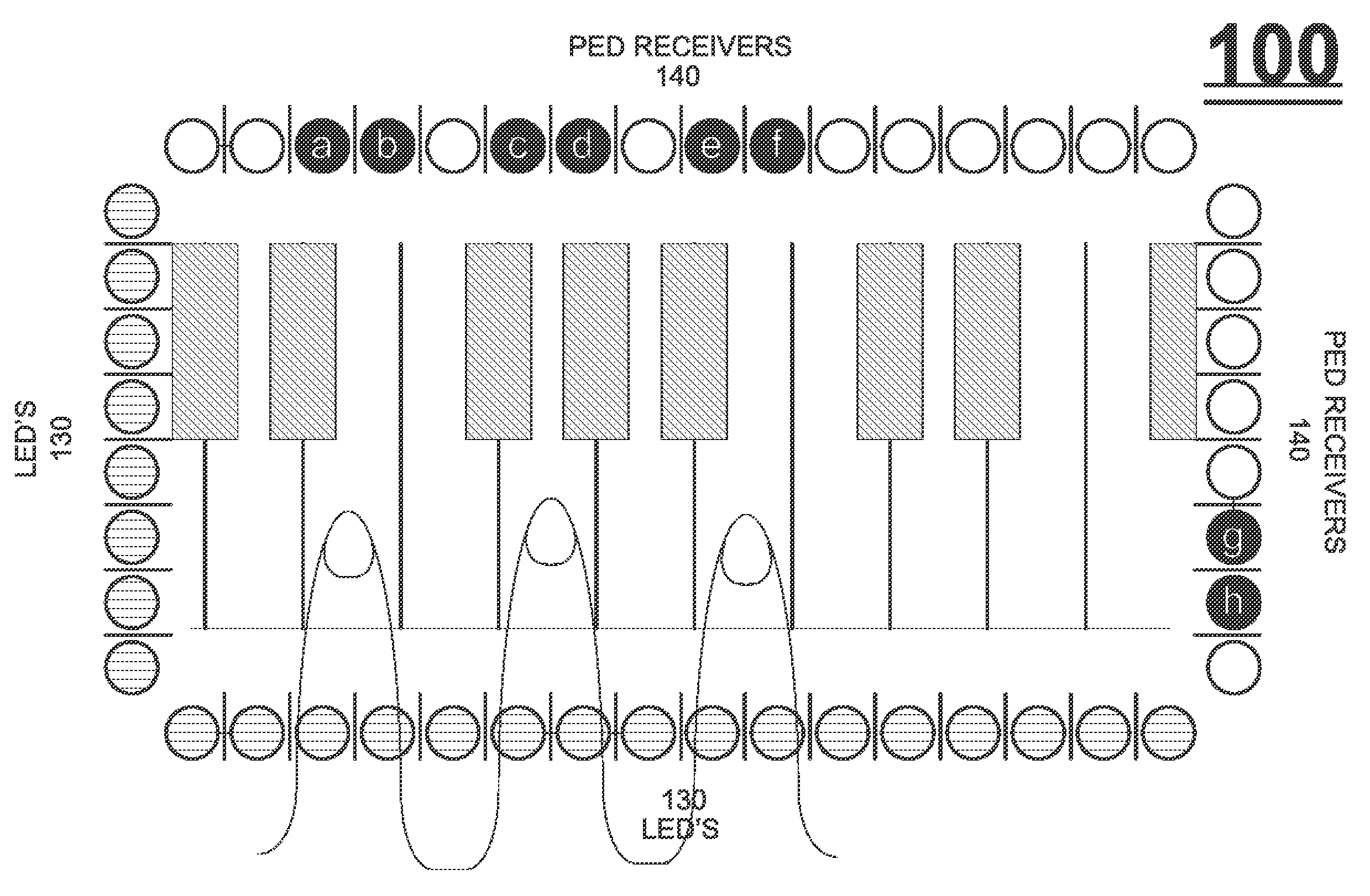
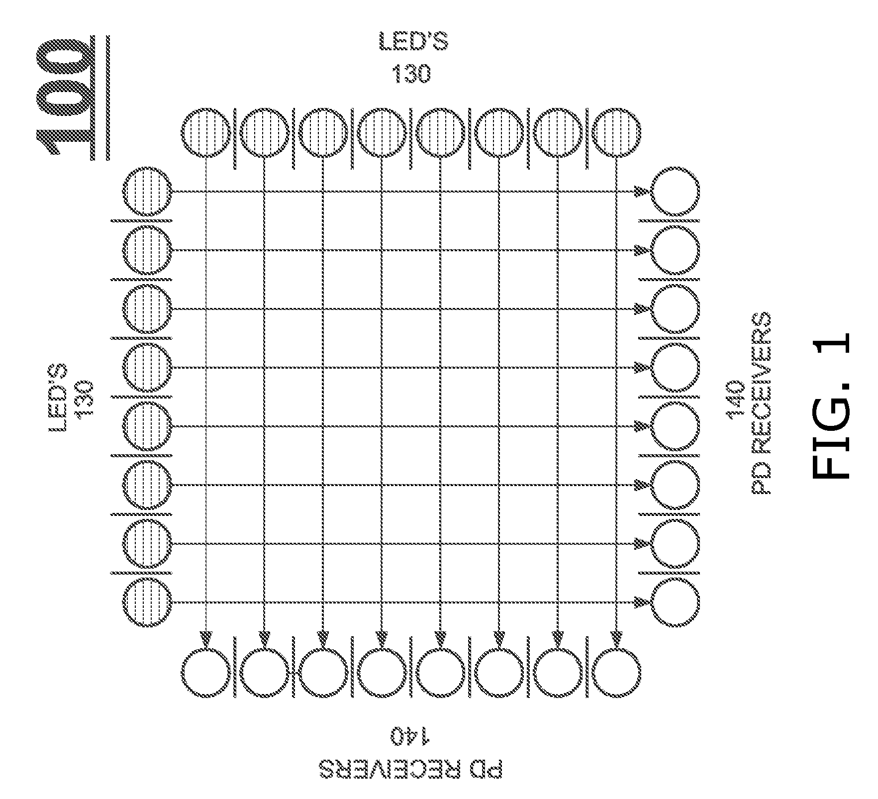
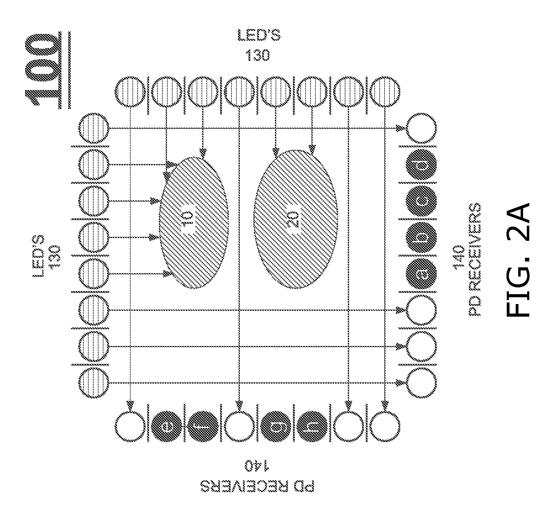
[0060]Aspects of the present invention relate to light-based touch screens. According to embodiments of the present invention, a light-based touch screen includes a plurality of infra-red light-emitting diodes (LEDs) and a plurality of photodiodes (PDs) arranged along the perimeter surrounding the screen. The LEDs project light substantially parallel to the screen surface, and this light is detected by the PDs. An object, such as a finger, placed over a portion of the screen blocks some of the light beams, and correspondingly some of the PDs detect less light intensity. The geometry of the locations of the PDs, and the light intensities they detect, suffice to determine screen coordinates of the object. The LEDs and PDs are controlled for selective activation and de-activation by a controller. Generally, each LED and PD has I / O connectors, and signals are transmitted to specify which LEDs and which PDs are activated.

[0061]In one embodiment of the present invention, plural LEDs are a...


PUM


Abstract

A light-based touch screen, including a housing for a display screen, a plurality of infra-red light emitting diodes (LEDs), fastened on the housing, for generating light beams, at least one LED selector, fastened on the housing and connected with the plurality of LEDs, for controllably selecting and deselecting one or more of the plurality of LEDs, a plurality of photodiode (PD) receivers, fastened on the housing, for measuring light intensity, at least one PD selector, fastened on the housing and connected with the plurality of PD receivers, for controllably selecting and deselecting one or more of the plurality of PD receivers, an optical assembly, fastened on the housing, for projecting light beams emitted by the plurality of LEDs in substantially parallel planes over the housing, and a controller, fastened on the housing and coupled with the plurality of PD receivers, (i) for controlling the at least one LED selector, (ii) for controlling the at least one PD selector, and (iii) for determining therefrom position and velocity of an object crossing at least one of the substantially parallel planes, based on output currents of the plurality of PD receivers.

Description

CROSS REFERENCES TO RELATED APPLICATIONS[0001]This application is a continuation-in-part of assignee's pending application U.S. Ser. No. 10 / 494,055, filed on Apr. 29, 2004, entitled ON A SUBSTRATE FORMED OR RESTING DISPLAY ARRANGEMENT.FIELD OF THE INVENTION[0002]The field of the present invention is touch screens for computers.BACKGROUND OF THE INVENTION[0003]Conventional touch screens are capacitance-based or resistance-based. These touch screens provide user interfaces through which a user enters input to a computing device by touching a screen at a selected location, with a stylus or with his finger.[0004]Conventional touch screens are generally large. When space is at a premium, such as with small handheld electronic devices, conventional touch screens are limited to only a few user inputs. Moreover, these inputs are not accurately interpreted when the user does not use a stylus.[0005]Conventional touch screens are also limited as to the types of user inputs that they can recogn...

Claims


Application Information

Patent Timeline
IPC IPC(8): G06F3/042
CPCG06F3/0421G06F2203/04108G06F3/0428G06F3/0425
Inventor GOERTZ, MAGNUSERIKSSON, THOMASSHAIN, JOSEPH
Owner NEONODE
Why Eureka
Try Eureka