Working apparatus and calibration method thereof

a technology of working apparatus and calibration method, which is applied in the direction of electrical programme control, program control, instruments, etc., can solve the problems of limiting the freedom of movement of the robot arm, large portion of the indicator surface and large blockage of the calibration jig pla

Inactive Publication Date: 2009-07-30
CANON KK
View PDF1 Cites 53 Cited by
  • Summary
  • Abstract
  • Description
  • Claims
  • Application Information

AI Technical Summary

Benefits of technology

[0010]The present invention was made in consideration of the above problems, and its exemplary embodiments provide an apparatus and method which allow execution of position calibration of a working unit even when a part of calibrating jig including a center of its markers is occluded during image measurement.

Problems solved by technology

(1) The publicly disclosed calibration methods do not make the assumption that a large portion of the indicator surface of the calibration jig is blocked.
However, in the case of a robot arm with multiple degrees of freedom, it is possible that a large part of the calibration jig plate is blocked by the robot arm, depending on its position and orientation.
However, because a large calibration jig plate can easily interfere with a robot arm or the floor, limiting the freedom of movement of operation of the robot arm, it is not suitable as a calibration jig.
(2) When the observational angle of the calibration jig plate becomes acute due to the position and orientation of the robot arm, the estimated precision can decrease significantly because the markers become difficult to observe.
Because there is a predetermined distance between the markers and the work reference points of the robot arm, if there is an error in the estimation of the positions and orientations of the markers, an error in the calculation of operation reference points can become amplified.
(4) While the work precision can be raised by using multiple cameras, an increase in the number of cameras makes avoiding problems (1) and (2) mentioned above more difficult.
However, as there is a necessity for the camera to be positioned somewhat directly in front of the markers using this method, this method is not suited to a case in which a jig is simultaneously measured using a plurality of cameras from a wide range of angles.
However, cited references 5 and 6 above do not assume the case in which the central part of the markers is hidden and cannot be captured, and the problem (1) mentioned above can occur.

Method used


Image

  • Working apparatus and calibration method thereof
  • Working apparatus and calibration method thereof
  • Working apparatus and calibration method thereof

Examples


first embodiment

[0028]In the first embodiment, a method of calibrating a position in three-dimensional space to increase the precision of work before a robot arm which is a working unit operates on a work which is a work subject will be given. In the present embodiment, image coordinates which are coordinates directly on an image and robot coordinates which are coordinates on an apparatus are calibrated without deriving camera parameters in advance.

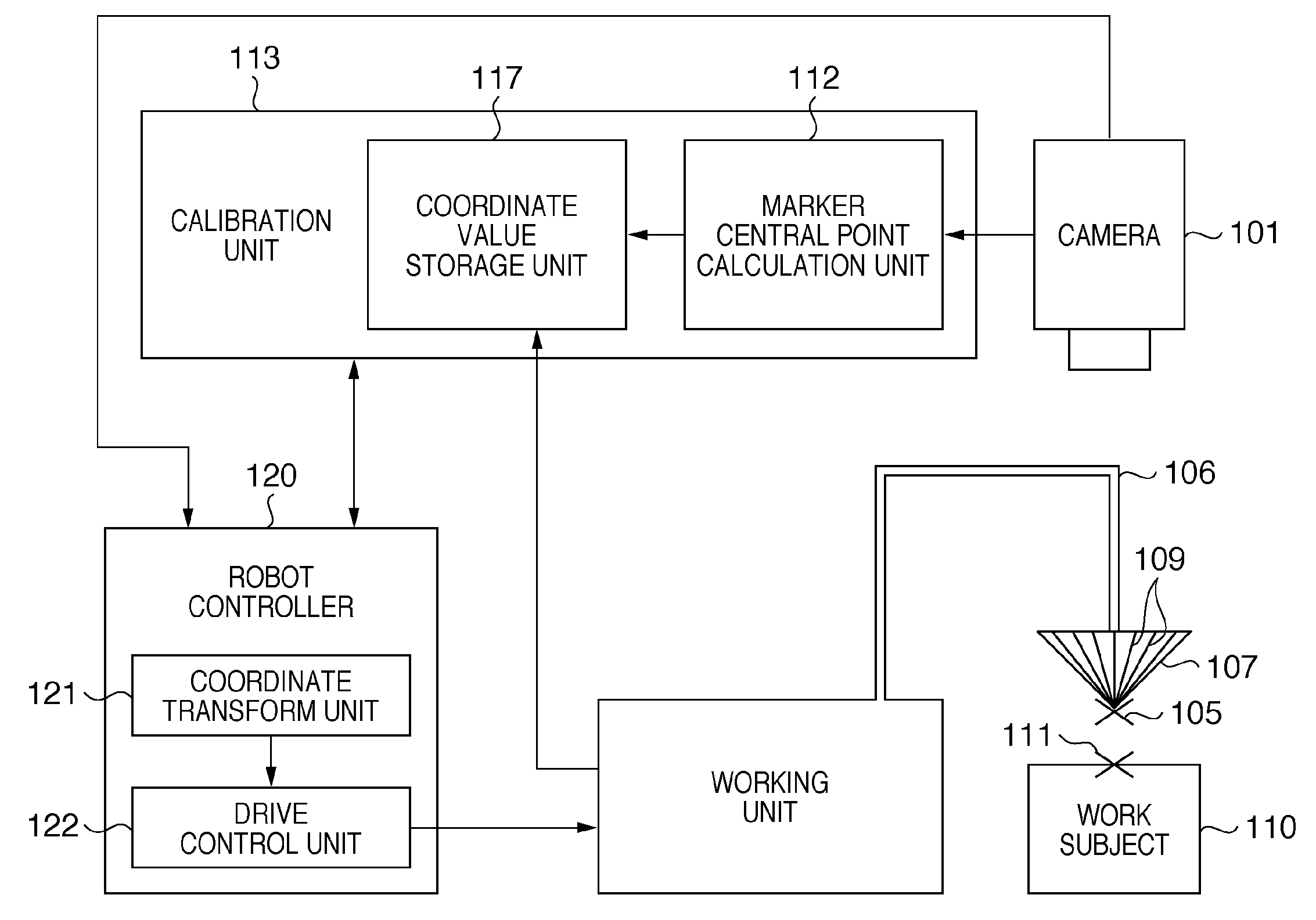
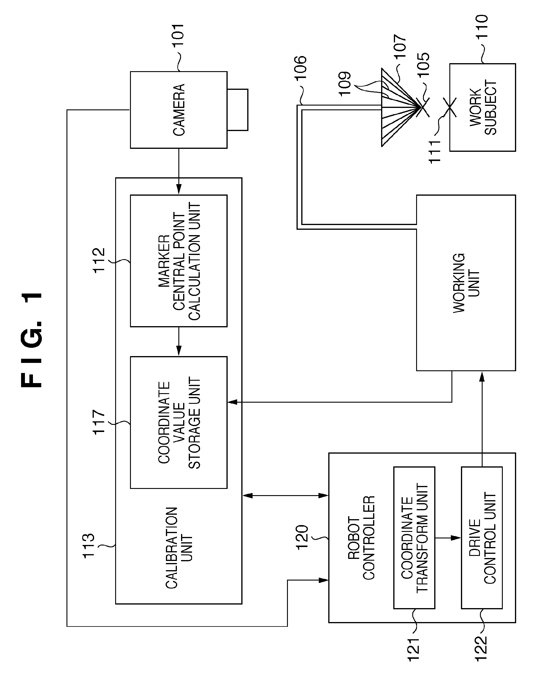
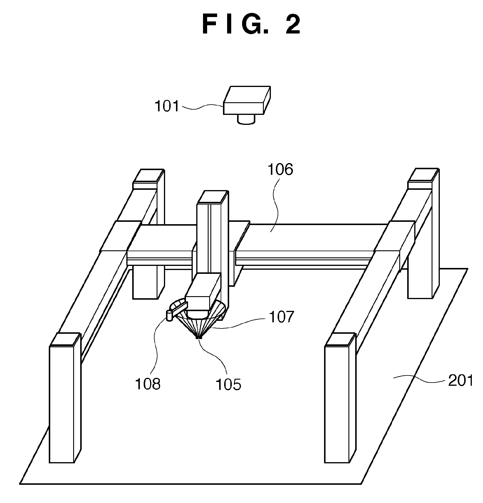
[0029]FIG. 1 is a block diagram illustrating a machine control apparatus and a robot as a controlled machine according to the first embodiment. Further, FIG. 2 is a perspective view illustrating a robot according to the first embodiment.

[0030]A robot controller 120 comprises a coordinate transform unit 121 and a drive control unit 122. A coordinate transform unit 121 transforms coordinates on an image captured by a camera 101 into robot coordinates which are coordinates on an apparatus. A drive control unit 122 controls the entire robot including a worki...

second embodiment

[0064]Next, as a second embodiment, a calibration method that does not use a laser distance meter 108 will be described. In this method, calibration of multiple degrees of freedom (DOF) robot arms other than XYZ orthogonal robot arms such as scalar or multiple perpendicular-joint robot arms is possible. In the second embodiment, a robot arm, the same calibration jig as that used in the first embodiment, and two or more cameras are used. By using a three-dimensional form for the markers, the markers can be stably observed from any angle, and a calibration reference point can be simultaneously observed from various angles. In the second embodiment, calibration reference points are observed by a plurality of cameras using these marker characteristics. Moreover, the composition of the second embodiment is mostly the same as that of the first embodiment (FIG. 1), and has a form in which a plurality of cameras 101 is connected.

[0065]Regarding the plurality of cameras 101, each camera para...

third embodiment

[0072]Next, as a third embodiment, and as derivative methods of the calibration processing explained in the second embodiment, methods which do not utilize calibration jigs such as those shown in FIGS. 3A through 3H or FIGS. 9A through 9C during calibration work will be given. In the present embodiment, first, 4 markers are distributed at predetermined positions on the robot arm. Next, in the same manner as in the second embodiment, a calibration jig is fixed and measured with a camera, and a calibration reference point and 4 markers are detected. These are transformed to world coordinates, and the positions in world coordinates of the reference point and 4 markers are acquired. Next, the relative positional relationships in world coordinates of the 4 markers and calibration reference point are stored. Next, the calibration jig is removed, and thereafter the position of the calibration reference point in world coordinates is determined from the relative positional relationships of t...


PUM


Abstract

A working apparatus comprises a working unit which executes work on a work subject, and a calibration jig on which a plurality of markers is arranged in a radial pattern from a center point of markers, the plurality of markers being arranged in three dimensions, and the calibration jig being attached to a working unit such that a calibration reference point set of a working unit coincides with a center point of markers. According to such a composition, it becomes possible to calibrate a position of a working unit even when a portion of the jig containing a center point of markers is occluded during image measurement.

Description

BACKGROUND OF THE INVENTION[0001]1. Field of the Invention[0002]The present invention relates to a working apparatus and calibration method thereof. In particular, the present invention relates to calibration of coordinates a working apparatus which controls a working unit having a machine using an image captured by an imaging means.[0003]2. Description of the Related Art[0004]Regarding assembly work and inspection using robotic arms, there is a practice in which a fixed camera detects the position and orientation of a work subject, and a robotic arm approaches and performs predetermined work. For this, a camera parameter which is a transform function between world coordinates and image coordinates, and forward and inverse kinematics that are transform mapping between robot sensor information and world coordinates must be known in advance. Because there is image strain originating from image capture in an image, and also because there is a small deviance due to mechanical error and ...

Claims


Application Information

Patent Timeline
Patent Type & Authority Applications(United States)
IPC IPC(8): G06K9/00H04N7/18G06F19/00B25J9/10B25J9/22G01B11/00G05B19/19G06T1/00
CPCG06T7/0042H04N1/00002H04N1/00827H04N1/00087H04N1/00344H04N1/00068G06T7/73
Inventor TATE, SHUNTAAOBA, MASATO
Owner CANON KK
Why Eureka
Try Eureka