Screw compressor

a screw compressor and compressor body technology, applied in the direction of machines/engines, liquid fuel engines, positive displacement liquid engines, etc., can solve the problem that the oil level detection means disposed in the interior of the screw compressor cannot be utilized, and achieve the effect of preventing damage to the bearings, reducing viscosity, and avoiding oil shortages

Active Publication Date: 2009-07-30
KOBELCO COMPRESSORS CORP
View PDF20 Cites 13 Cited by
  • Summary
  • Abstract
  • Description
  • Claims
  • Application Information

AI Technical Summary

Benefits of technology

[0008]It is an object of the present invention to provide a screw compressor having rotor shafts disposed horizontally and bearings for supporting the rotor shafts, the bearings being lubricated by an oil bath method, the screw compressor permitting accurate confirmation of the level of oil present within a bearing casing and being not likely to cause oil shortage in the bearings.

Problems solved by technology

When rotors are rotating in the screw compressor, oil level detecting means disposed in the interior of the screw compressor cannot be utilized because the oil level at the bottom of the bearing casing is oscillating due to splash of oil.

Method used


Image

  • Screw compressor
  • Screw compressor
  • Screw compressor

Examples


Embodiment Construction

[0022]An embodiment of the present invention will be described below with reference to the accompanying drawings.

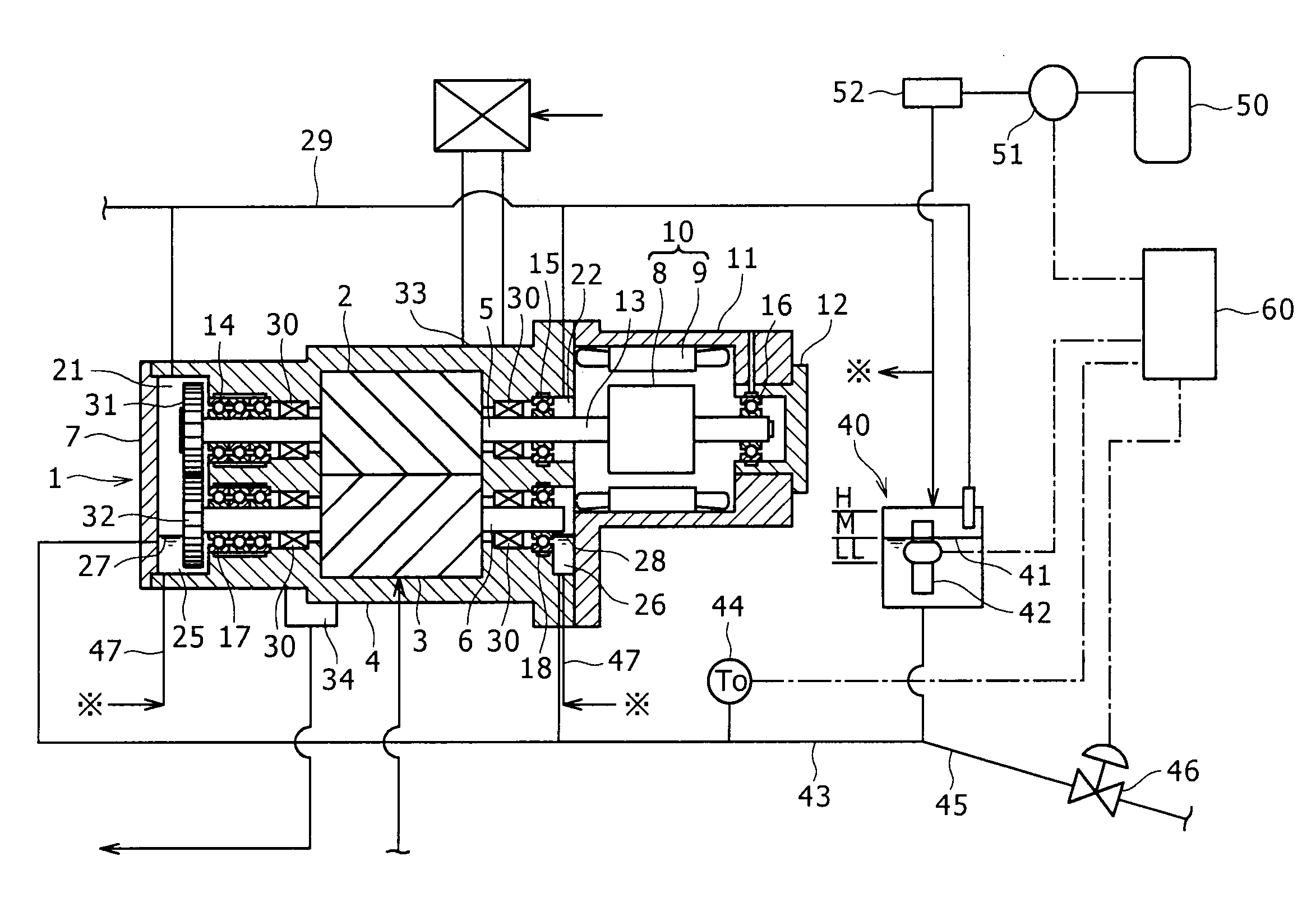
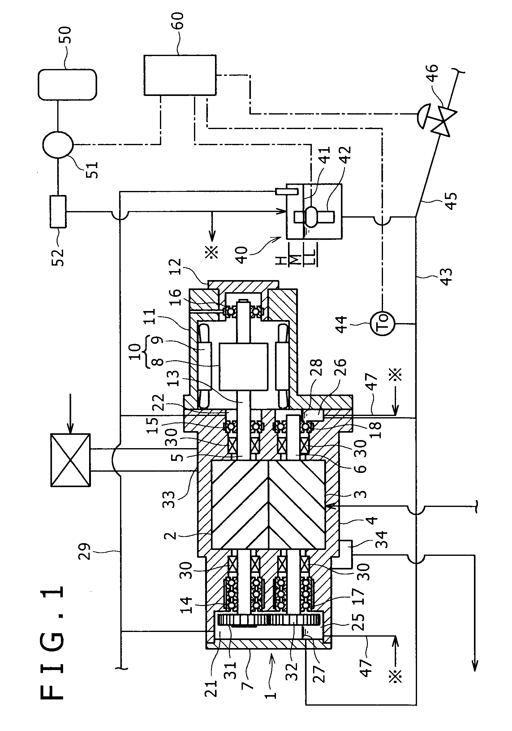
[0023]FIG. 1 illustrates a screw compressor 1 according to an embodiment of the present invention. The screw compressor 1 is a water lubrication type screw compressor wherein screw rotors 2 and 3 are cooled and lubricated with water. In the screw compressor 1, a pair of male rotor 2 and female rotor 3 meshing with each other are accommodated within a rotor casing 4. Rotor shafts 5 and 6 of the rotors 2 and 3 are disposed horizontally. One end of the rotor casing 4 is closed with a cover 7, while to an opposite end of the rotor casing 4 is mounted a motor casing 11 which accommodates a motor 10 composed of a rotor 8 and a stator 9. An end portion of the motor casing 11 is also closed with a cover 12. The rotor shaft 5 of the male rotor 2 and a motor shaft 13 of the motor 10 share an integrally-formed shaft (separate rotor shaft 5 and motor shaft 13 may be coupled together ...


PUM


Abstract

A screw compressor is disclosed wherein a pair of rotor shafts are disposed horizontally and an oil sump is formed at the bottom of a bearing casing which accommodates bearings for supporting the rotor shafts, a bearing lower portion being soaked into oil present in the oil sump for lubrication. The screw compressor comprises a chamber provided separately from the bearing casing, an oil line for communication between the oil sump in the bearing casing and the chamber and oil level detecting means disposed in the chamber. According to this structure, the oil level in the bearing casing can be checked accurately and there is no fear of oil shortage in the bearings.

Description

BACKGROUND OF THE INVENTION[0001]1. Field of the Invention[0002]The present invention relates to a screw compressor.[0003]2. Description of the Related Art[0004]In a conventional screw compressor having a pair of male and female screw rotors with rotor shafts disposed in the horizontal direction, a timing gear and bearings are mounted on each of the rotor shafts and are lubricated and cooled with oil to prevent damage thereof.[0005]In connection with the related art, an oil bath method is mentioned as a general lubricating method used in case of low- or medium-speed rotation. In the oil bath method it is desirable to install an oil gauge and thereby make it possible to check the oil level easily so that the oil level lies at the center of a bottom roller in principle. However, when it is intended to adopt the oil bath method for lubrication of bearings and timing gears in a positive-displacement compressors such as, for example, a screw compressor, it may not always be possible to i...

Claims


Application Information

Patent Timeline
Patent Type & Authority Applications(United States)
IPC IPC(8): F01C21/04
CPCF01C21/04F04C18/16F04C2270/86F04C29/021F04C2240/809F04C28/28F04C18/18
Inventor YOSHIMURA, SHOJINOGUCHI, TORU
Owner KOBELCO COMPRESSORS CORP
Why Eureka
Try Eureka