
Apparatus for controlling lighting angle of headlights of vehicle

a technology for controlling the lighting angle of headlights and vehicles, applied in process and machine control, instruments, navigation instruments, etc., can solve problems such as the inability to driv

Active Publication Date: 2008-10-23
DENSO CORP +1
View PDF5 Cites 13 Cited by
  • Summary
  • Abstract
  • Description
  • Claims
  • Application Information

AI Technical Summary

Benefits of technology

[0007]The present invention has been made in light of the circumstances described above, and has as its object to provide a headlight lighting angle control apparatus, which enables a driver of the vehicle to make a more accurate visual confirmation, in advance, of a line shape of a curve the vehicle is going to enter.
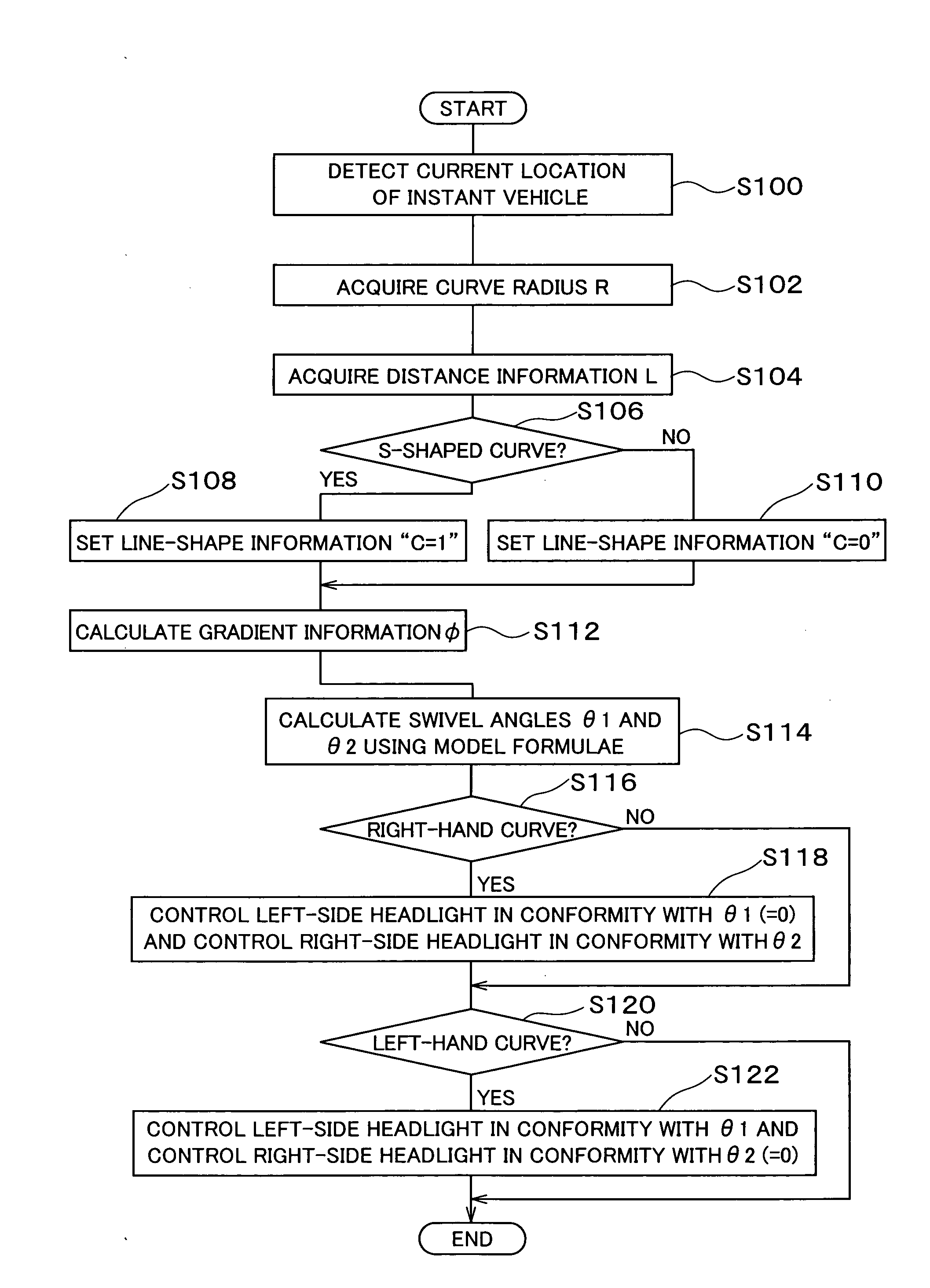
[0010]In the case where, for example, the curve the vehicle is going to enter has a line shape successively turning in different directions as in an S-shaped curve, the lighting angle of the headlights is controlled in conformity with the line shape of the near side curve. Then, the lighting angle of the headlights is quickly controlled in conformity with the line shape of the following curve. In the conventional headlight lighting angle control apparatus mentioned above, the timing for actually starting control of the lighting angle of the headlights falls immediately before the actual entry of the instant vehicle into the curve. Accordingly, this may delay the timing for lighting the headlights for the driver to visually confirm the line shape of the near side curve, which may possibly disable the driver to make a visual confirmation of the line shape of the following curve. In this regard, the configuration mentioned above may enable calculation of the lighting angle of the headlights, watching over not only the line shape of the near side curve but also the line shape of the following curve, because the line-shape information acquired through the line-shape information acquiring means is the result of the determination on whether or not the curve is an S-shaped curve. Thus, the vehicle driver can make a more accurate visual confirmation of the line shape of the curve the vehicle is going to enter.
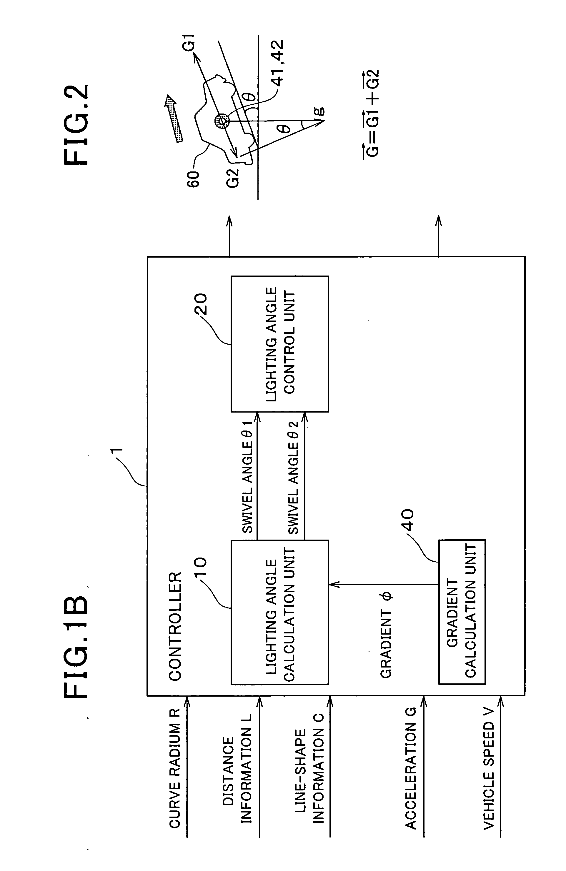
[0013]In the case where the curve the instant vehicle is going to enter is an ascending slope, for example, the distance lit by the headlights of the instant vehicle will be shorter than in the case of a flat road. In this regard, since the configuration mentioned above allows the lighting angle calculation unit to calculate the lighting angle of the headlights on the basis of the gradient information, the lighting angle control of the headlights can be performed taking into account of the gradient of the road. Thus, the vehicle driver can make a more accurate visual confirmation of the line shape of the curve the vehicle is going to enter.
[0016]In the case where a curve the instant vehicle is going to enter has a line shape successively turning in different directions as in the case, for example, of an S-shaped curve, the lighting angle of the headlights are controlled in conformity with the line shape of the near side curve. Then, the lighting angle of the headlights is quickly controlled in conformity with the line shape of the following curve. In the conventional headlight lighting angle control apparatus mentioned above, the timing for actually starting control of the lighting angle of the headlights falls immediately before the actual entry of the instant vehicle into the curve. Therefore, this may delay the timing for lighting the headlights for the driver to visually confirm the line shape of the near side curve, which may possibly disable the driver to make a visual confirmation of the line shape of the following curve. Further, the inventors confirmed that, in the case where a curve the instant vehicle is going to enter is an ascending slope, for example, the distance ahead of the vehicle lit by the headlights is shorter than in the case of a flat road.

Problems solved by technology

Accordingly, this may delay the timing for lighting the headlights for the driver to visually confirm the line shape of the near side curve, which may possibly disable the driver to make a visual confirmation of the line shape of the following curve.

Method used


Image

  • Apparatus for controlling lighting angle of headlights of vehicle
  • Apparatus for controlling lighting angle of headlights of vehicle
  • Apparatus for controlling lighting angle of headlights of vehicle

Examples


Embodiment Construction

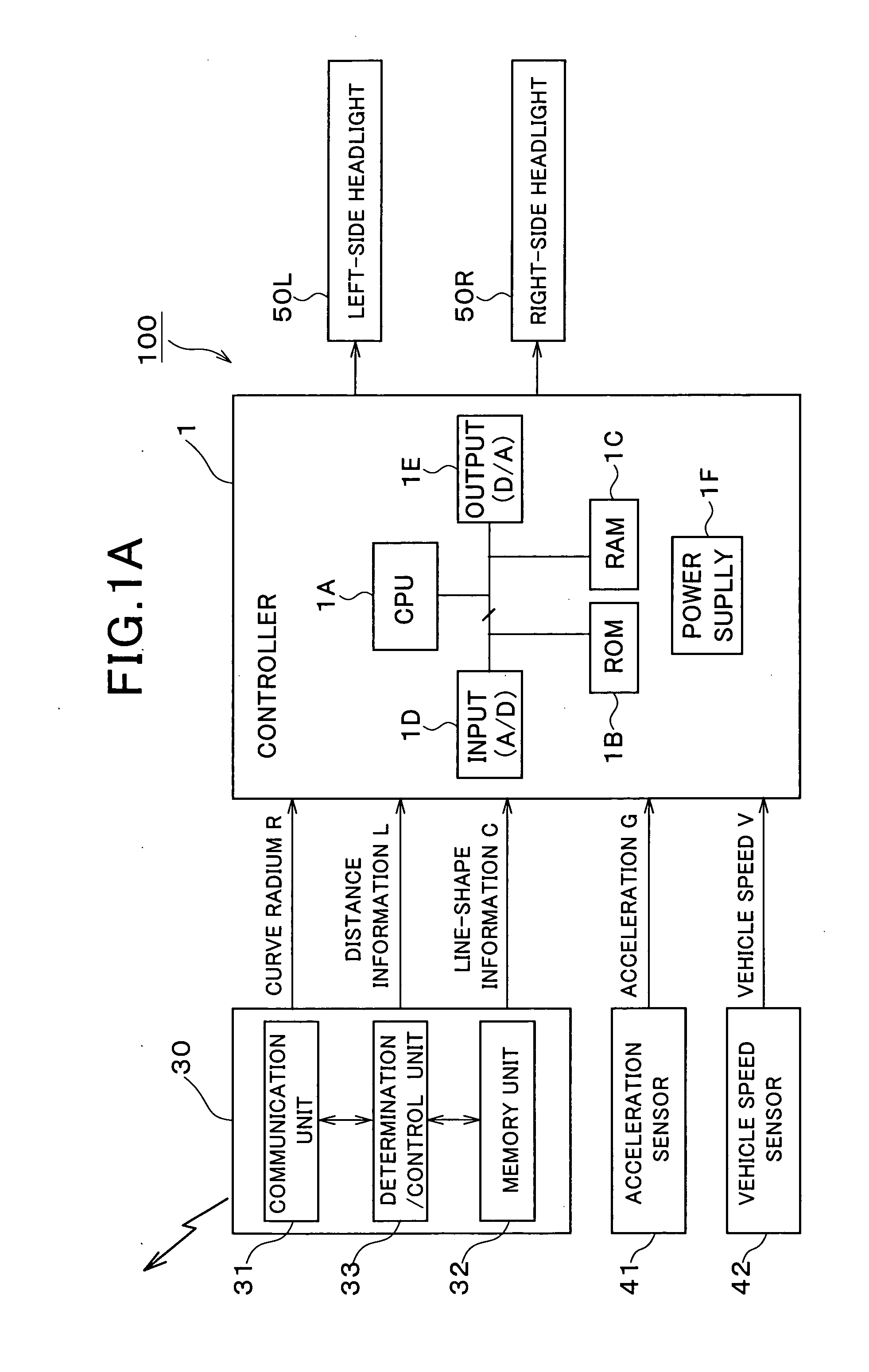
[0032]Referring to FIGS. 1 to 3, hereinafter will be described a headlight lighting angle control apparatus according to an embodiment of the present invention. FIG. 1A is a block diagram generally illustrating a headlight lighting angle control apparatus 100 according to the present embodiment.

[0033]As shown in FIG. 1A, the headlight lighting angle control apparatus 100 basically includes a controller (or processor) 1 for executing various calculations, a car navigation apparatus 30 for acquiring various pieces of information on the road on which the vehicle equipped with the apparatus travels, an acceleration sensor 41 for detecting acceleration applied to the vehicle, a vehicle speed sensor 42 for detecting speed of the vehicle based on wheel speed, a light-side headlight 50L for lighting ahead of the vehicle on the left, and a right-side headlight 50R for lighting ahead of the vehicle on the right.

[0034]The car navigation apparatus 30 includes a communication unit 31 for making ...


PUM


Abstract

An apparatus is provided to control a lighting angel of headlights installed in a vehicle. In the apparatus, a curve of the road is calculated and the radius of the curve is obtained, based on the current position and the road information. The curve is located ahead of the vehicle. A distance from the current position to a starting point of the curve is calculated based on the current position and the road information. Determination is made as to whether or not the curve is an S-shaped curve based on the road information, and line-shape information showing a line shape of the S-curve is set in response to the determination results of the curve. A lighting angle of the headlights is calculated based on the radius of the curve, the distance and the line-shape information, and the lighting angle of the headlights is controlled based on the calculated lighting angle.

Description

CROSS-REFERENCE TO RELATED APPLICATION[0001]This application is based on and claims the benefit of priority from earlier Japanese Patent Application No. 2007-010696 filed Jan. 19, 2007, the description of which is incorporated herein by reference.BACKGROUND OF THE INVENTION[0002]1. Technical Field of the Invention[0003]The present invention relates to a headlight lighting angle control apparatus for controlling lighting angle of headlights installed in a vehicle.[0004]2. Related Art[0005]The technique of this art has been well known as disclosed, for example, in Japanese Patent Application Laid-Open Publication No. 2003-072460. The technique disclosed in this literature uses wheel speed which is detected by a wheel speed sensor for detecting wheel speed of the vehicle, and steering angle which is detected by a steering angle sensor for detecting steering angle of the steering wheel of the vehicle. Based on the wheel speed and the steering angle, the lighting angle of the headlights ...

Claims


Application Information

Patent Timeline
Patent Type & Authority Applications(United States)
IPC IPC(8): G02B26/08G06F19/00B60Q1/04B60Q1/08B60Q1/12
CPCB60Q1/12B60Q2300/112B60Q2300/114B60Q2300/322B60Q2300/331
Inventor MORISHITA, MASAHIKOHAGIWARA, TORU
Owner DENSO CORP
Learn More