Endoscope
- Summary
- Abstract
- Description
- Claims
- Application Information
AI Technical Summary
Benefits of technology
Problems solved by technology
Method used
Image
Examples
first embodiment
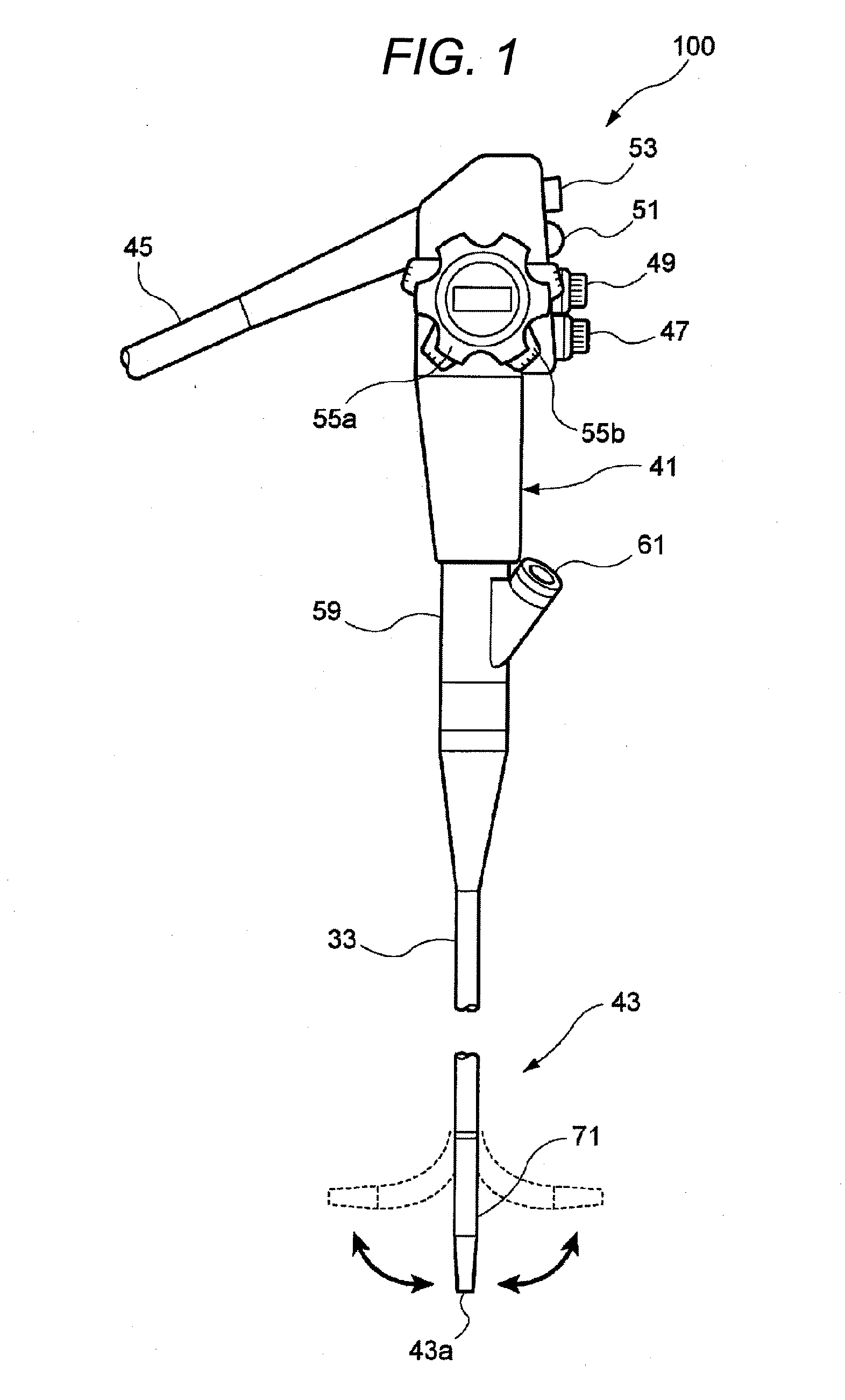
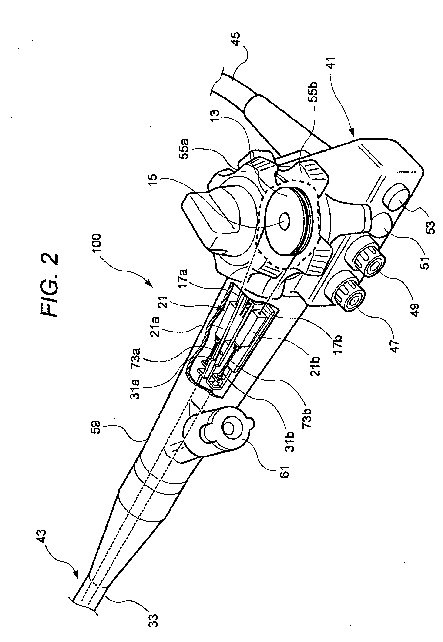
[0042]FIG. 1 is an entire configuration diagram of an endoscope according to the invention, and FIG. 2 is a partially cutaway perspective view of an operating portion shown in FIG. 1. In addition, description will be made with the same reference numerals being given to the same members as the members shown in FIG. 12.
[0043]An endoscope 100 includes an operating portion 41, and an insertion portion 43 connected to the operating portion 41 and inserted into an abdominal cavity. A universal cable 45 is connected to the operating portion 41, and a light guide connector (not shown) is provided at the tip of the universal cable 45. The light guide connector is detachably connected to a light source, and illumination light is sent to an illumination optical system at a tip 43a of the insertion portion. Additionally, an electrical connector is connected to the light guide connector, and this electrical connector is detachably connected to a processor.
[0044]An air supply / water supply button ...
second embodiment
[0058]Next, the endoscope according to the invention will be described.
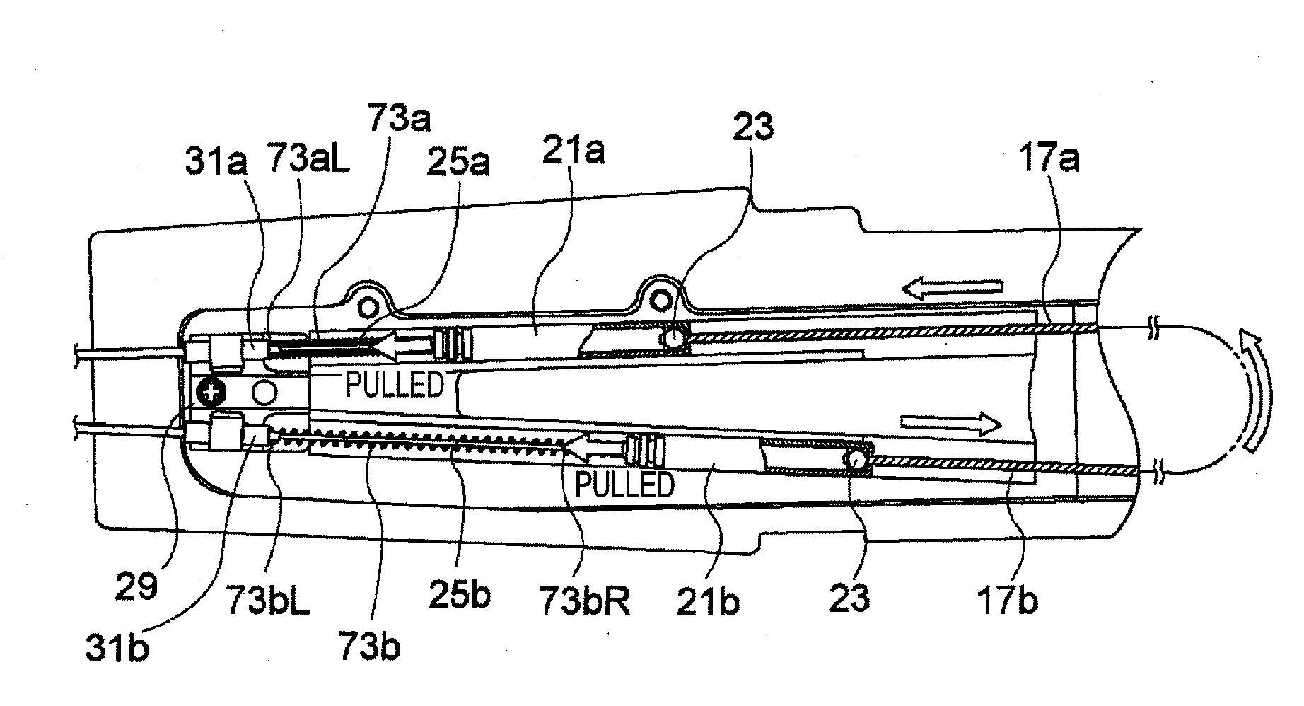
[0059]FIG. 6 is an enlarged plan view of the inside of an operating portion according to the second embodiment to which coil springs are fixed, and FIG. 7 is an explanatory view of the operation of the second embodiment. In addition, in the following respective embodiments, the same reference numerals will be given to the same members as the members shown in FIGS. 1 to 5, and duplicate description will be omitted. In this endoscope, one ends (left ends) 73aL and 73bL of the coil springs 73a and 73b are fixed to the wire-receiving members 31a and 31b, respectively, and the other ends (right ends) 73aR and 73bR thereof are fixed to the sleeves 21a and 21b, respectively.
[0060]According to this endoscope, both ends of the coil springs 73a and 73b are fixed to the wire-receiving members 31a and 31b and the sleeves 21a and 21b. Thereby, even if the distance between the wire-receiving members 31a and 31b and the sleeves...
third embodiment
[0062]Next, the endoscope according to the invention will be described.
[0063]FIG. 8 is an enlarged plan view the inside of an operating portion according to the third embodiment in which compression spring members are provided inside sleeves, respectively, FIG. 9 is an explanatory view of the operation of the third embodiment, and FIG. 10 is an explanatory view showing the operation of a compression spring member.
[0064]In this endoscope, as shown in FIG. 8, compression spring members 75a and 75b which biases the slip-off preventing members 23 toward the operating wires 17a and 17b are provided inside the sleeves 21a and 21b, respectively. The compression spring members 75a and 75b may be coil springs which are housed in a compressed state. A left end of each spring member abuts on the engaging tube 65, and the other end thereof abuts on the slip-off preventing member 23. The compression spring members 75a and 75b may be proper spring members, such as leaf springs, besides the coil s...
PUM
 Abstract
Description
Claims
Application Information
 - R&D
- Intellectual Property
- Life Sciences
- Materials
- Tech Scout
- Unparalleled Data Quality
- Higher Quality Content
- 60% Fewer Hallucinations
Browse by: Latest US Patents, China's latest patents, Technical Efficacy Thesaurus, Application Domain, Technology Topic, Popular Technical Reports.
© 2025 PatSnap. All rights reserved.Legal|Privacy policy|Modern Slavery Act Transparency Statement|Sitemap|About US| Contact US: help@patsnap.com


