Method and Apparatus for Orchestration of Fracture Placement From a Centralized Well Fluid Treatment Center

a well fluid treatment and fracture technology, applied in the direction of fluid removal, survey, borehole/well accessories, etc., can solve the problems of increasing the cost of fracture placement, and requiring not only movement and equipment movement, so as to maximize the unnatural reach of the second fracture and maximize the fracture contact

Active Publication Date: 2009-08-06
HALLIBURTON ENERGY SERVICES INC
View PDF54 Cites 168 Cited by
  • Summary
  • Abstract
  • Description
  • Claims
  • Application Information

AI Technical Summary

Benefits of technology

[0006]In general, one aspect of the invention features a method for inducing multiple fractures in a subterranean formation associated with a plurality of wells within a region by utilizing a centralized well treatment fluid center. In particular, this invention introduces a new approach to maximize fracture contact into the unnatural direction; e.g. perpendicular or at least oblique to the naturally preferred fracture direction; using the minimum required fracture placement in the field. The centralized well treatment fluid center is configured for fracturing a plurality of wells. The centralized well treatment fluid center is adapted to manufacture and pump a well treatment fluid. A first fracture is induced at a first well location by flowing well treatment fluid from the centralized well treatment fluid center to the first well location. The first fracture alters one or more first well location stress fields in the subterranean formation. One or more first well location effects of the one or more first well location stress fields from the first fracture are measured. The time delay is determined before the second fracture is induced. The determination of the time delays is based, at least in part, on at least one of the one or more first well location effects in order to maximize the unnatural reach of the second fracture. A second well location for fracturing is selected. The selection of the second well location is based, at least in part, on the maximum reorientation due to the one or more first well location effects. The second fracture at the second well location is induced after the time delay by flowing well treatment fluid from the centralized well treatment fluid center to the second well location. The second fracture alters one or more second well location stress fields in the subterranean formation.

Problems solved by technology

Several costs are associated with this process of fracturing multiple wells located at a single well pad or multiple well pads sequentially in a field.
For example, each fracture induced requires not only time for movement and set up of equipment but also incurs monetary costs which may become substantial for a given field.
Further, obtaining maximum production from a previously producing oil well may require additional fracturing as the producing well as when damage occurs due to factors such as fine migration in the subterranean formation.
Such additional fracture increases the monetary costs associated with production of a field.
While such methods increase the number of locations for drainage into the wellbore, they are generally not optimal, as they tend to avoid good producing reservoirs.
Conventional methods do not introduce new directions for hydrocarbons to flow into the wellbore.
The conventional method may also not account for, or even more so, utilize, stress alterations around existing fractures when inducing new fractures in order to connect to previously unattained reservoirs.
Further, typical methods rely on the complex movement of equipment and personnel to sequentially service wells.

Method used


Image

  • Method and Apparatus for Orchestration of Fracture Placement From a Centralized Well Fluid Treatment Center
  • Method and Apparatus for Orchestration of Fracture Placement From a Centralized Well Fluid Treatment Center
  • Method and Apparatus for Orchestration of Fracture Placement From a Centralized Well Fluid Treatment Center

Examples


Embodiment Construction

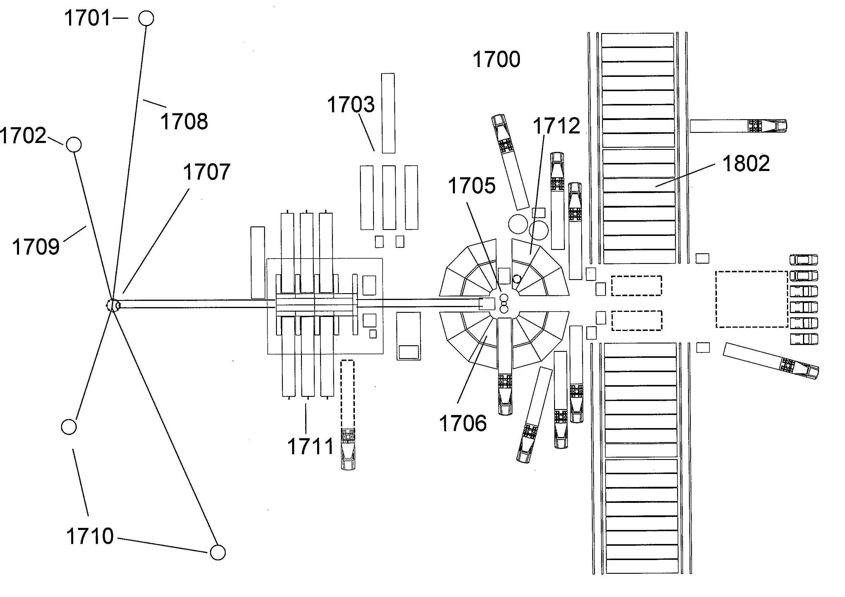
[0084]The present invention relates generally to methods for orchestrating the inducement of multiple fractures in a subterranean formation for a region and more particularly to methods to induce a first fracture at a first well location with a first orientation in a formation followed by determinations of a time delay and according to stress field effects of the first fracture or of the region to optimize the inducement of a second fracture with a second angular orientation in the formation either at the first well location or a different well location. The fractures are induced by flowing well treatment fluid from a centralized well treatment fluid center that has been adapted to flow well treatment fluid to a plurality of wells in order to perform substantially simultaneous or sequential fracturing.

[0085]The methods and apparatus of the present invention may allow for increased well productivity by the introduction of multiple fractures at different angular dispositions relative ...


PUM


Abstract

A method and apparatus for orchestrating multiple fractures at multiple well locations in a region by flowing well treatment fluid from a centralized well treatment fluid center is disclosed that includes the steps of configuring a well treatment fluid center for fracturing multiple wells, inducing a fracture at a first well location, measuring effects of stress fields from the first fracture, determining a time delay based in part upon the measured stress effects, inducing a second fracture after the time delay at a second location based upon the measured effects, and measuring the stress effects of stress fields from the second fracture. Sensors disposed about the region are adapted to output effects of the stress fields. Location and orientation of subsequent fractures is based on the combined stress effects of the stress fields as a result of the prior fractures which provides for optimal region development.

Description

CROSS-REFERENCE TO RELATED APPLICATIONS[0001]This application is a continuation in part of U.S. patent application Ser. No. 11 / 291,496 filed on Dec. 1, 2005, U.S. patent application Ser. No. 11 / 396,918 filed on Apr. 3, 2006, U.S. patent application Ser. No. 11 / 545,749 filed on Oct. 10, 2006 and U.S. patent application Ser. No. 11 / 753,314 filed on May 24, 2007 which are each hereby incorporated by reference as if fully reproduced herein.FIELD OF THE INVENTION[0002]The present invention relates generally to methods for orchestrating the inducement of multiple fractures in a plurality of well locations in a subterranean formation for a region to obtain optimal production from a plurality of wells with minimal required fracturing. More particularly, the present invention relates to methods to induce a first fracture at a well location with a first orientation in a formation followed by determinations of a time delay and according to stress field effects to optimize the inducement of a s...

Claims


Application Information

Patent Timeline
Patent Type & Authority Applications(United States)
IPC IPC(8): E21B43/26E21B47/00
CPCE21B43/26E21B43/30E21B43/267
Inventor SURJAATMADJA, JIM B.HOWELL, MATT T.CASE, LEONARDROBINSON, LONNIE R.
Owner HALLIBURTON ENERGY SERVICES INC
Why Eureka
Try Eureka