Wet cement dispensing apparatus with cleaning and access features

a technology of wet cement and dispensing equipment, which is applied in the direction of liquid transfer devices, movable measuring chambers, instruments, etc., can solve the problems of difficult, sometimes impossible, and difficult to deliver grout to elevated areas with little overhead space, and achieve the effect of preventing excessive grout run-out and easy cleaning

Inactive Publication Date: 2009-08-06
LANG DAMIAN L
View PDF21 Cites 1 Cited by
  • Summary
  • Abstract
  • Description
  • Claims
  • Application Information

AI Technical Summary

Benefits of technology

[0009]It is therefore the purpose of this invention to provide a grout dispensing apparatus that is easy to clean and capable of delivering grout to elevated and difficult to reach locations. It is a further purpose of this invention to provide such a grout dispensing apparatus that also prevents excessive grout run-out after being shut off.

Problems solved by technology

One problem associated with grout delivery systems of the type described is that it is difficult, and sometimes impossible, to deliver grout to elevated areas that offer little overhead space.
This can be a severe limitation, because many work areas do not provide the requisite amount of overhead space and therefore necessitate alternative, more cumbersome means of grout application.
Another common problem among conventional grout dispensers is the difficulty associated with cleaning.
However, much of the interior of the auger tube is difficult to reach, particularly the portions of the tube's interior that are closest to its longitudinal center.
Yet another problem associated with traditional grout dispensers is excessive grout run-out after the motorized auger has been deactivated.

Method used


Image

  • Wet cement dispensing apparatus with cleaning and access features
  • Wet cement dispensing apparatus with cleaning and access features
  • Wet cement dispensing apparatus with cleaning and access features

Examples


Embodiment Construction

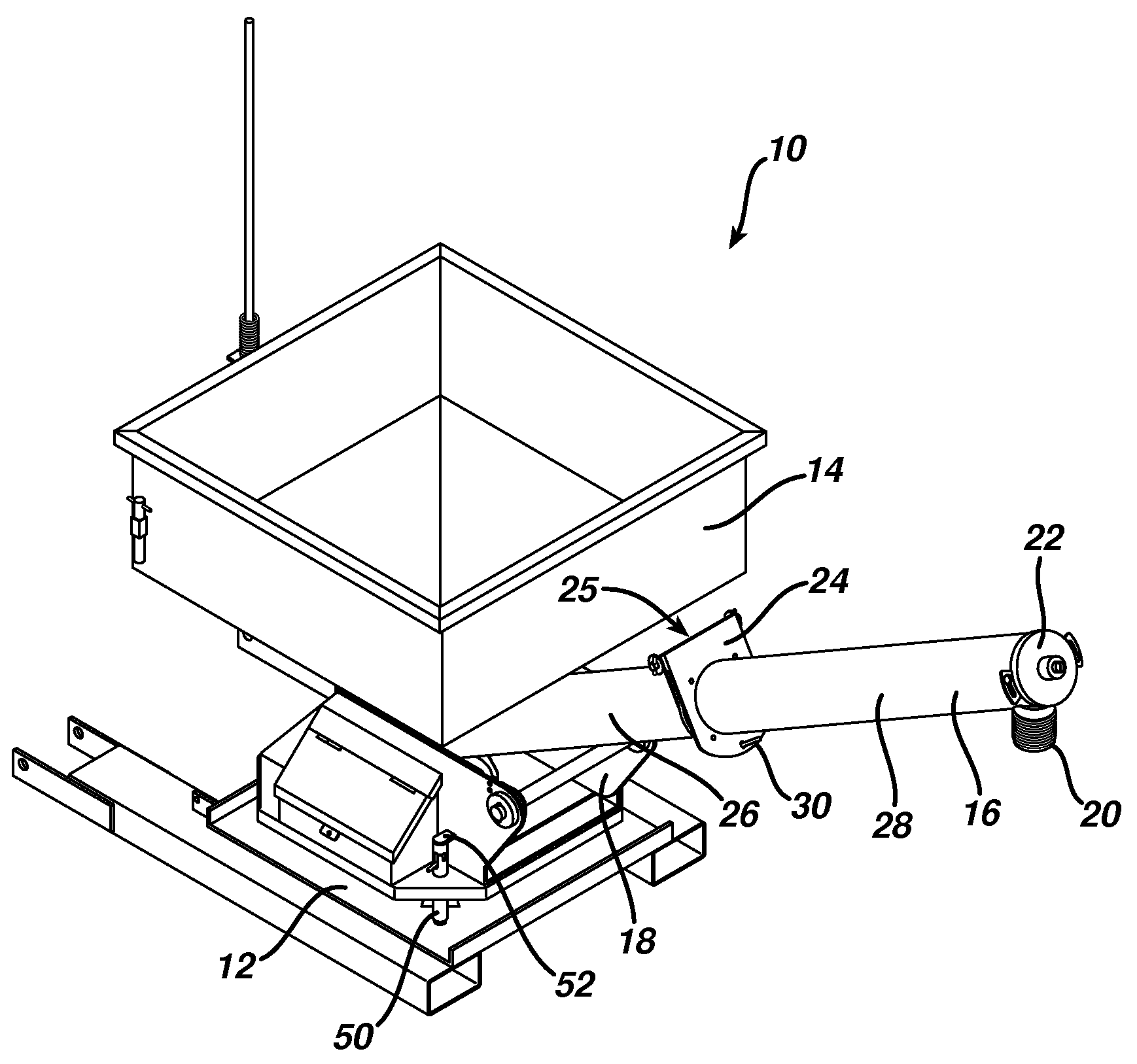
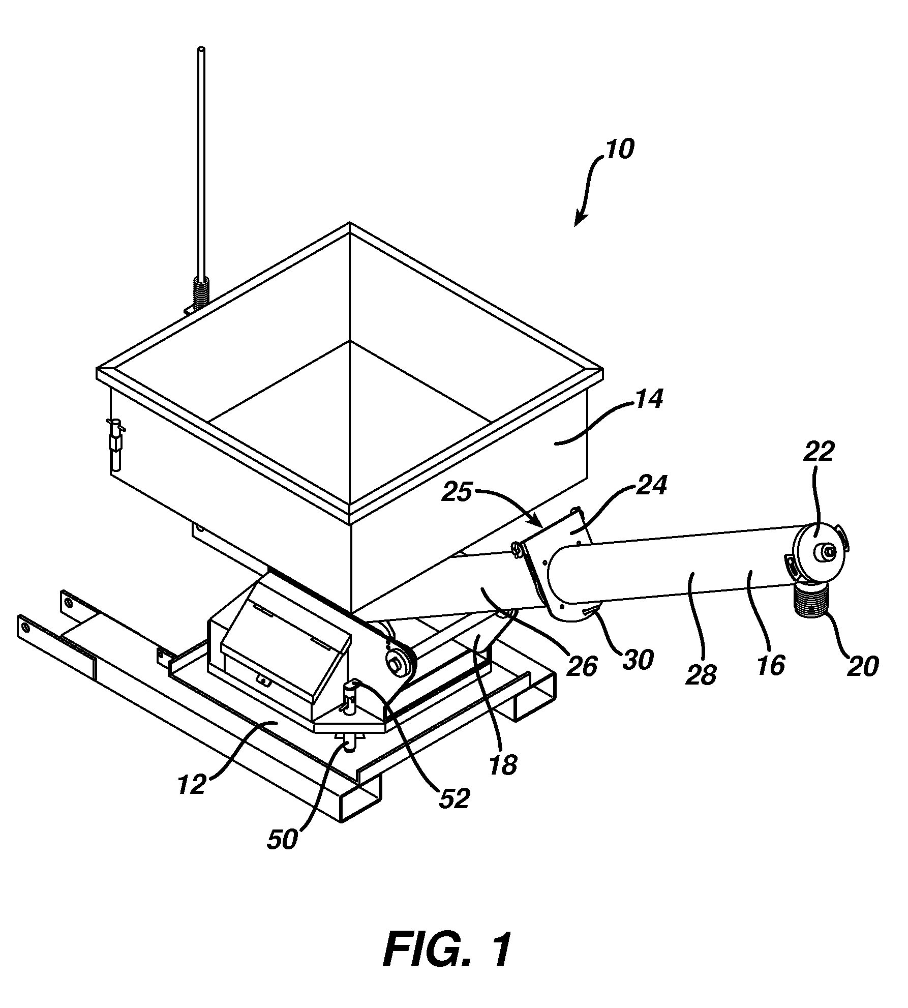
[0021]Referring to FIG. 1, the grout dispenser 10 has a base 12, a hopper 14, and an auger tube 16 containing a conventional, motorized auger. All components of the dispenser are fabricated from steel unless otherwise noted, although all other durable, rigid materials, such as composites, aluminum, and plastic, are also contemplated. Terms such as “vertical”, “horizontal”, “top”, and “bottom” are used herein to describe the orientation and position of components when the dispenser is seated on a flat surface in an operable orientation.

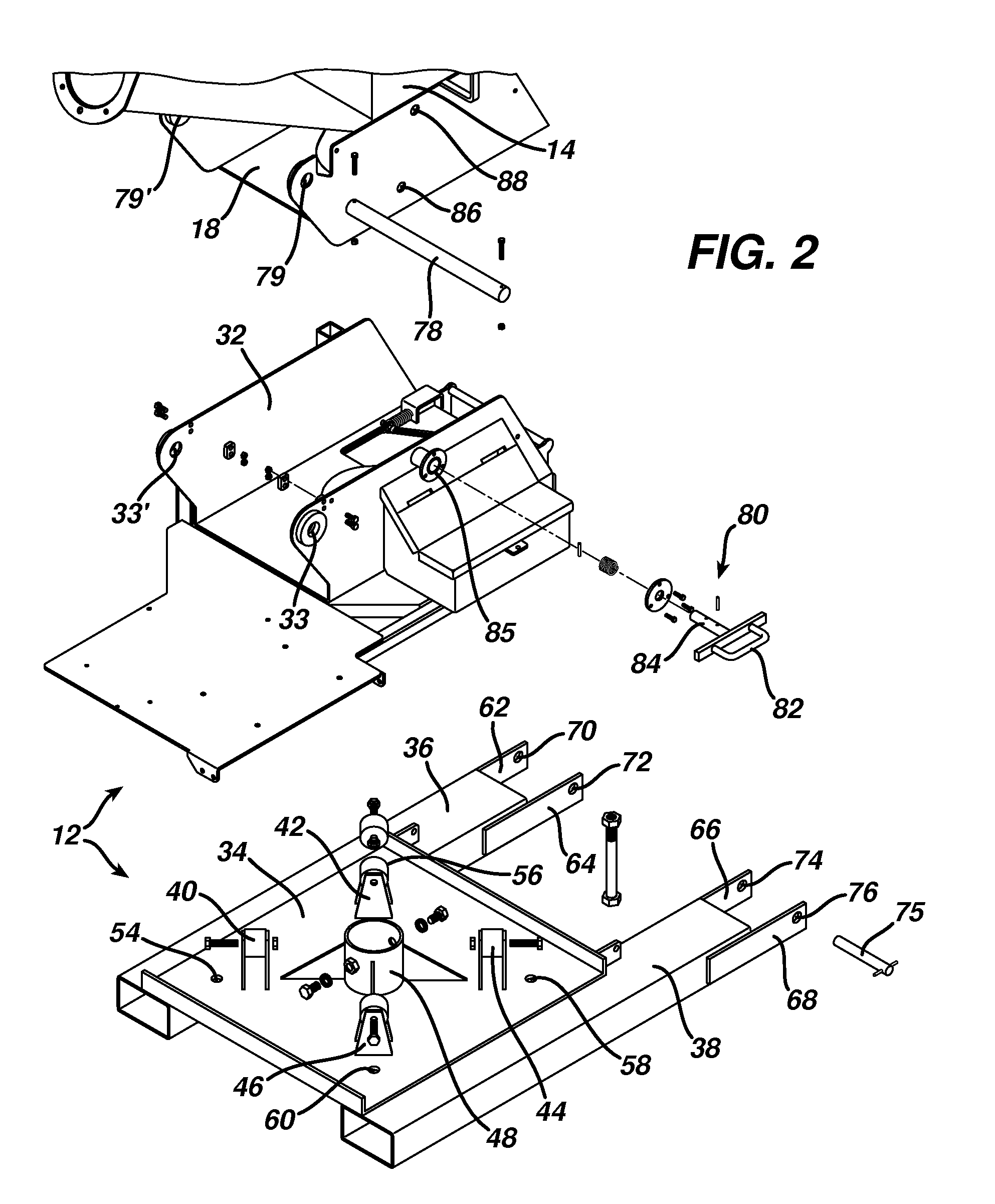
[0022]The hopper 14 is a box-shaped container that is wider at its top end than its bottom end in order to “feed” fluent material downwardly along vertical and sloped sidewalls. The top of the hopper 14 is open for accepting grout, such as from a larger container, and the bottom of the hopper is open to the auger tube 16 for dispensing grout. Additionally, a U-shaped cradle 18 is rigidly affixed to the bottom of the hopper 14.

[0023]The auger tube 16 is...


PUM


Abstract

An improved wet cement dispensing apparatus having a tilting hopper and a hinged, angled auger tube for aiding in the cleaning of the apparatus and for delivering grout to elevated and hard to reach locations. The hopper can be locked in a first position for dispensing grout and in a tilted position for cleaning. The hopper rotates about a vertical axis. The dispensing end of the auger tube preferably extends to near the top edge of the hopper.

Description

BACKGROUND OF THE INVENTION[0001]1. Field of the Invention[0002]This invention relates generally to the field of wet cement dispensers and more particularly to a wet cement dispensing apparatus having a tilting hopper and a hinged, angled auger tube for aiding in the cleaning of the apparatus and for delivering grout to elevated and hard to reach locations.[0003]2. Description of the Related Art[0004]Traditional wet cement (i.e., “grout”) dispensers such as those described in U.S. Pat. No. 6,112,955 to Lang and U.S. Pat. No. 6,206,249 to Lang, which are herein incorporated by reference, combine a hopper for holding grout and an auger tube containing a motorized auger that extends horizontally from the bottom of the hopper for conveying the grout a short distance away from the hopper. Typically, a flexible hose extends from the end of the auger tube for accurately channeling grout to the area where it is to be applied.[0005]In the sequence of normal operation, a cement truck or other...

Claims


Application Information

Patent Timeline
Patent Type & Authority Applications(United States)
IPC IPC(8): B67D5/64G01F11/20B67D7/84
CPCE04G21/20
Inventor LANG, DAMIAN L.
Owner LANG DAMIAN L
Why Eureka
Try Eureka