Sheet conveying device

a conveying device and sheet technology, applied in the direction of thin material handling, electrographic process equipment, instruments, etc., to achieve the effect of simple structure and facilitate the user to remove a jammed

Inactive Publication Date: 2009-08-06
KONICA MINOLTA BUSINESS TECH INC
View PDF9 Cites 8 Cited by
  • Summary
  • Abstract
  • Description
  • Claims
  • Application Information

AI Technical Summary

Benefits of technology

[0007]An object of the present invention is to provide a sheet conveying de

Problems solved by technology

When a paper jam occurs, the jammed sheet is stuck

Method used


Image

  • Sheet conveying device
  • Sheet conveying device
  • Sheet conveying device

Examples


Embodiment Construction

[0023]Sheet conveying devices according to preferred embodiments of the present invention are described with reference to the accompanying drawings.

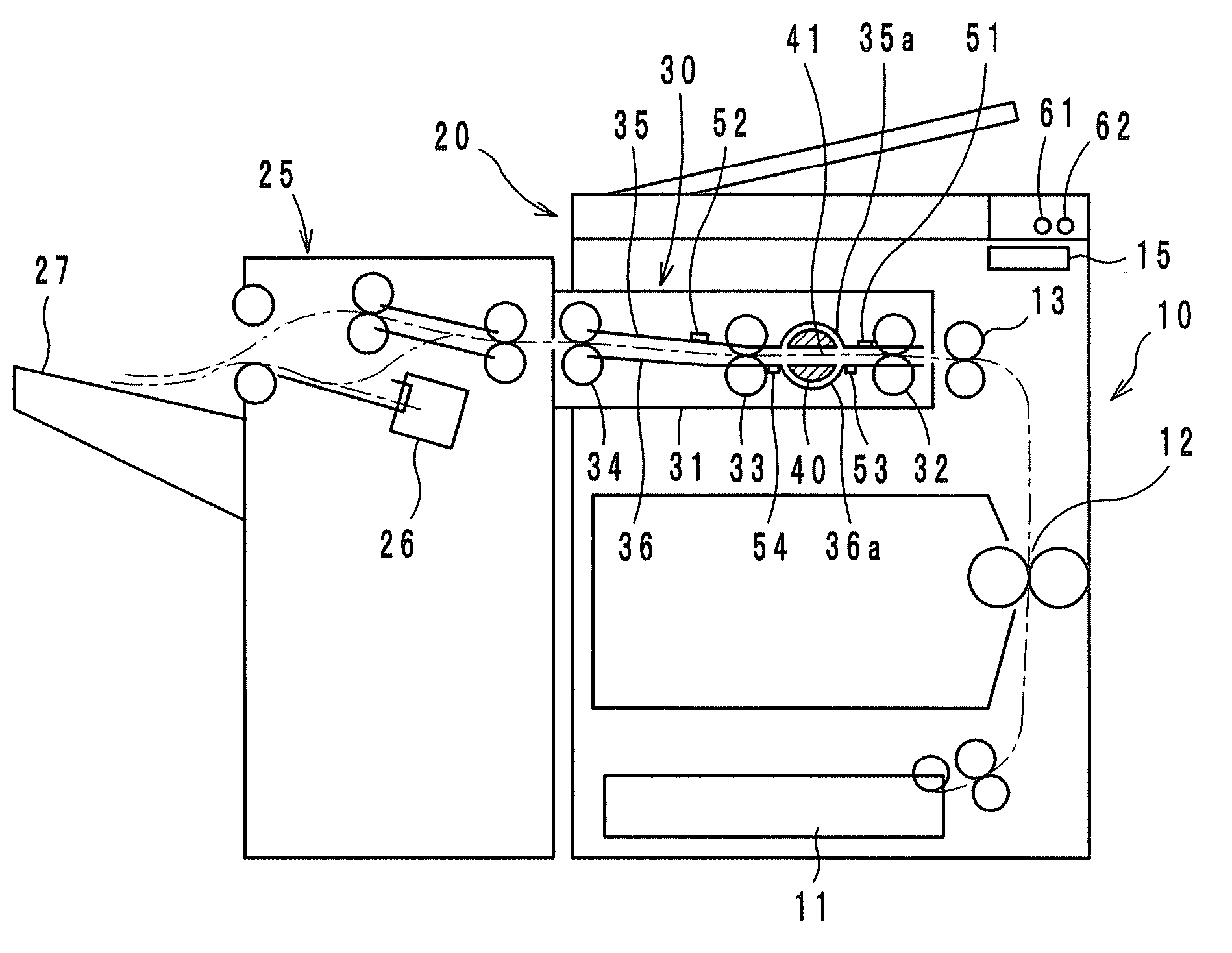
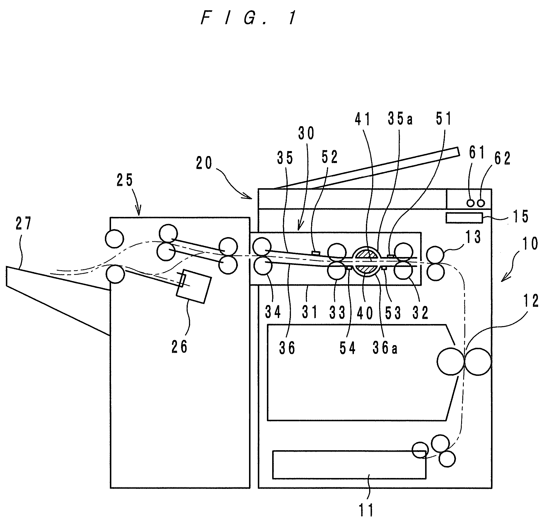
[0024]As shown by FIG. 1, an image forming system provided with a sheet conveying device according to an embodiment of the present invention generally comprises a printer body 10, an image reader 20, a finisher 25 having a stapler 26, etc. and a sheet conveying device 30 for conveying printed sheets from the printer body 10 to the finisher 25. The devices other than the sheet conveying device 30 are well known, and descriptions thereof are omitted. In FIG. 1, the long and short dashed line indicates a sheet path. A sheet is conveyed from a sheet feed unit 11 to a transfer section 12, and then onto a tray 27 of the finisher 25 via a pair of ejection rollers 13 and the sheet conveying device 30.

[0025]The sheet conveying device 30 comprises a housing 31, conveyer rollers 32, 33 and 34 for conveying sheets one by one, guide plates 35 and 36 ...


PUM


Abstract

A sheet conveying device having conveyer rollers for conveying sheets one by one, a jam treater having a space and sheet guides for regulating a front side and a back side of a conveyed sheet. In the space of the jam treater, a sheet is guided, and the jam treater is rotatable and can be drawn out of a housing of the sheet conveying device. The sheet guides have curved portions to form a space in which the jam treater rotates. In order to remove a jammed sheet from a sheet path in the sheet conveying device, an operator rotates the jam treater to wind the jammed sheet around the jam treater and draws the jam treater together with the jammed sheet out of the housing.

Description

[0001]This application is based on Japanese application No. 2008-022513 filed on Feb. 1, 2008, the content of which is incorporated herein by reference.BACKGROUND OF THE INVENTION[0002]1. Field of the Invention[0003]The present invention relates to a sheet conveying device suited to be employed in an image forming apparatus, such as an electrophotographic copying machine, a printer or the like, or in a finisher for finishing (for example, stapling) sheets ejected from the image forming apparatus.[0004]2. Description of Related Art[0005]In image forming apparatuses, such as copying machines and printers, and in finishers, paper jams are inevitable. In treating such a paper jam, generally, an operator removes the jammed sheet manually. If the jammed sheet is out of the operator's reach, the operator should rotate a conveyer roller by hand to move the jammed sheet. Also, if necessary, the operator should detach a sheet conveying section from the apparatus body so as to make a space for...

Claims


Application Information

Patent Timeline
IPC IPC(8): G03G15/00
CPCB65H29/008B65H2801/06B65H2601/11B65H29/125
Inventor MORITA, RYO
Owner KONICA MINOLTA BUSINESS TECH INC
Why Eureka
Try Eureka