Solar Roof Tracker

a solar roof and tracker technology, applied in the direction of heat collector mounting/support, photovoltaic supports, light and heating equipment, etc., can solve the problems of structural and/or regulatory margins, the most currently available photovoltaic panel steering system is too large and/or too heavy to be cost-effectively mounted on most roofs, etc., and achieves efficient capture and conversion of solar energy

Inactive Publication Date: 2009-08-13
COLLINS KENNETH D +1
View PDF21 Cites 66 Cited by
  • Summary
  • Abstract
  • Description
  • Claims
  • Application Information

AI Technical Summary

Benefits of technology

[0004]Accordingly, an aspect of the invention involves a solar tracking and mounting system for two-dimensional arrays of small to medium sized photovoltaic panels ideally suited for installation on the pitched or the flat roofs of residential houses or industrial buildings. The solar tracking and mounting system includes a plurality of solar tracking assemblies that carry the photovoltaic panels and slowly steer the panels to more often directly face the sun as it moves across the sky daily and through the annual seasons. As a result, the solar tracking and mounting system creates significantly more electricity from the sunlight than if the panels were mounted in a fixed position. The solar tracking assemblies are interconnected in a modular and adaptable fashion which allows installations to be configured in different shapes and interpanel spacing depending on size, pitch, and orientation of each roof surface and any roof penetrations or obstructions that it might have.

Problems solved by technology

A problem recognized by the inventors is that most currently available photovoltaic panel steering systems are too large and / or too heavy to be cost-effectively mounted on most roofs, which often have odd shapes, view obstruction restrictions, and minimal structural and / or regulatory margins for added weight.

Method used


Image

  • Solar Roof Tracker
  • Solar Roof Tracker
  • Solar Roof Tracker

Examples


Embodiment Construction

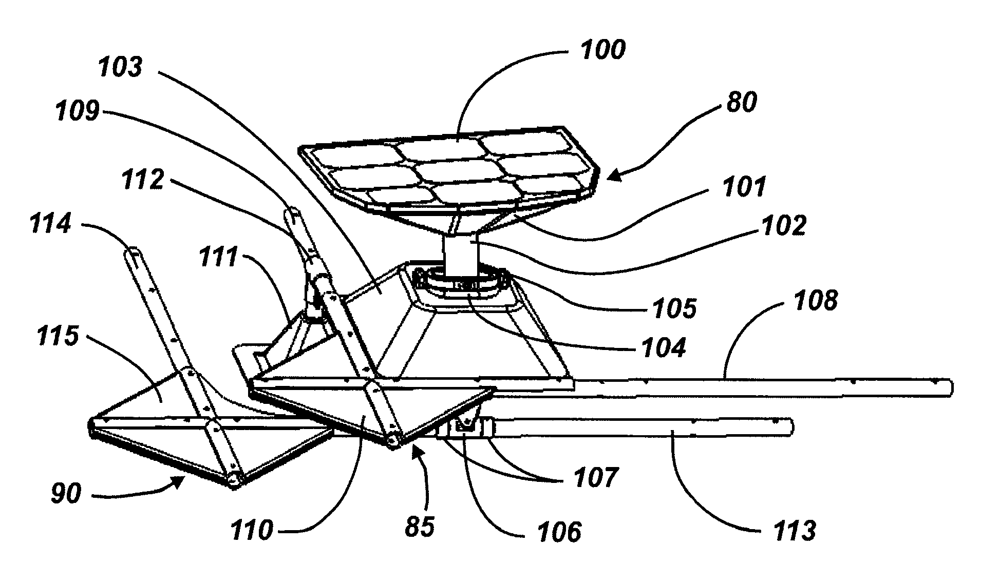
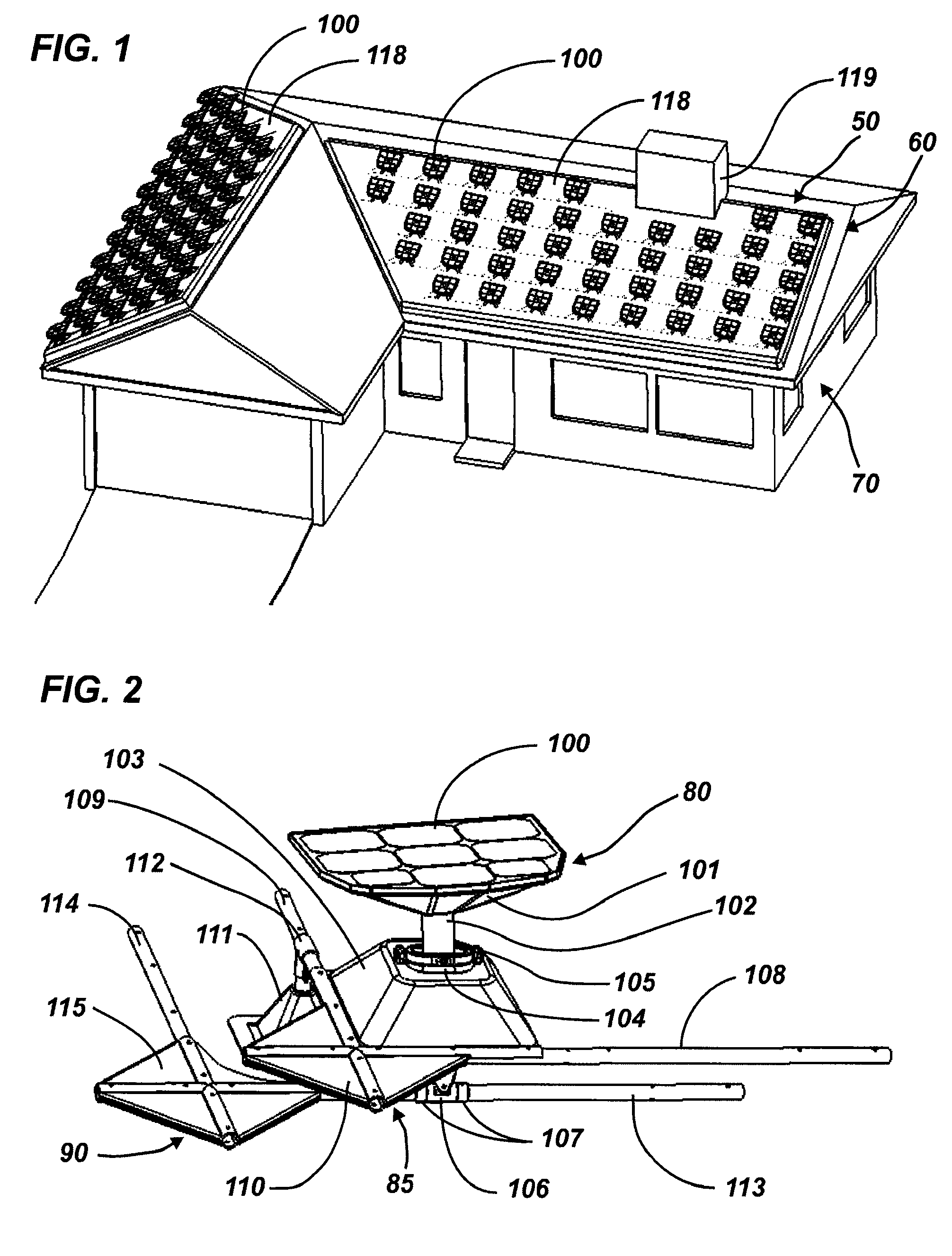
[0027]With reference to FIGS. 1-6, an embodiment of a rooftop solar tracking and mounting system 50 will be described. The rooftop solar tracking and mounting system 50 will be shown and described as being mounted onto a pitched rooftop 60 of a residential house 70, on the most favorably sun-facing sections of the rooftop 60. In one or more embodiments, the rooftop solar tracking and mounting system 50 is mounted onto a pitched, flat, or curved rooftop of a house, commercial building, or other building. In further embodiments, the solar tracking and mounting system 50 is mounted onto the ground or pitched, flat, or curved structure(s) other than a house or building.

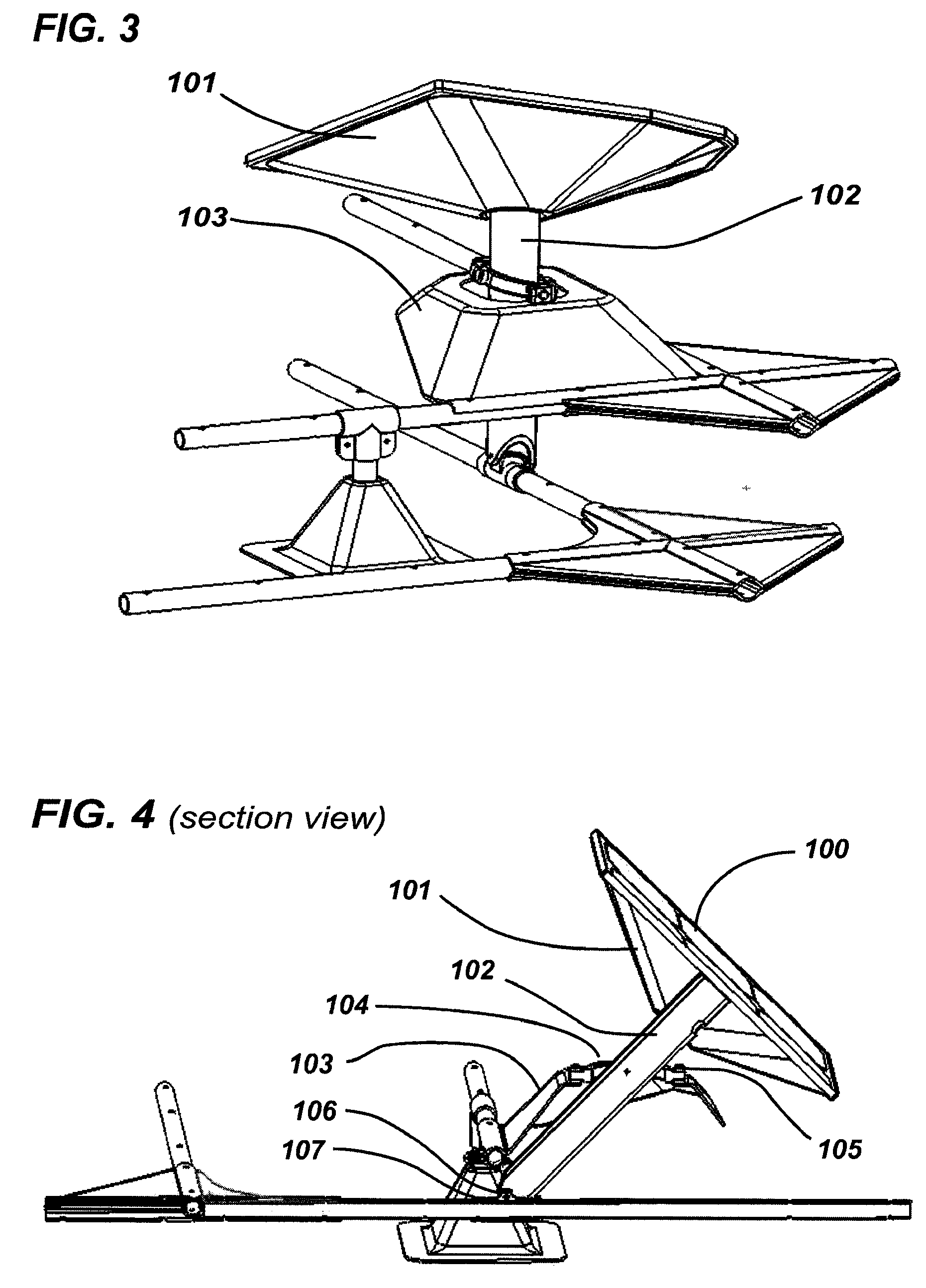
[0028]The rooftop solar tracking and mounting system 50 includes a plurality of individual solar tracking assemblies 80 interconnected by a fixed upper lattice assembly 85 and a lower movable lattice assembly 90.

[0029]Each solar tracking assembly 80 includes a plurality of small to medium sized photovoltaic panels 100 mou...


PUM


Abstract

A solar tracking system for mounting on a roof having one or more rooftop planar surfaces includes an array of solar tracking assemblies for at least one of the one or more rooftop planar surfaces, each array of solar tracking assemblies mountable at substantially the same orientation on the rooftop planar surface, each solar tracking assembly including a mounting structure, a steering mechanism, and one or more energy converting units that convert solar energy into electrical energy, the steering mechanism supported at least in part by the mounting structure and the one or more energy converting units steered by the steering mechanism; a drive mechanism that drives multiple steering mechanisms of the array of solar tracking assemblies; and a control processor that controls the drive mechanism so that the one or more energy converting units follow the sun.

Description

CROSS-REFERENCE TO RELATED APPLICATION[0001]This application claims the benefit of provisional patent application Nos. 61 / 027,614 and 61 / 027,617, each filed Feb. 11, 2008, under 35 U.S.C. 119(e). These provisional patent applications are incorporated by reference herein as though set forth in full.BACKGROUND OF THE INVENTION[0002]Roof-mounted photovoltaic panels have been in use for many years. The photovoltaic panels are usually mounted onto a roof of a building at a fixed angle. The photovoltaic panels are mounted to the roof at a location and an angle that attempts to maximize the capture and conversion of solar energy into electrical energy given the particular orientations and pitch angles of the available roof sections. It is known that photovoltaic panels produce more electrical energy when they are dynamically steered in one or preferably two axis so that the panels are perpendicular to the sun for more hours during each day. A problem recognized by the inventors is that mos...

Claims


Application Information

Patent Timeline
Patent Type & Authority Applications(United States)
IPC IPC(8): F24J2/38F24J2/46F24S50/20
CPCF24J2/405F24J2/52F24J2/5424F24J2002/5451H02S20/23Y02B10/12Y02B10/20Y02E10/47F24J2002/5468F24S25/00F24S30/455F24S50/60F24S2030/131F24S2030/136Y02B10/10Y02E10/50
Inventor COLLINS, KENNETH D.COLLINS, FOSTER D.
Owner COLLINS KENNETH D
Why Eureka
Try Eureka