

Residential solar thermal power plant
A kind of thermal energy equipment and solar technology, applied in the field of solar thermal energy system, can solve the problem of large hole width of concentrator
- Summary
- Abstract
- Description
- Claims
- Application Information
AI Technical Summary
Problems solved by technology
Method used
Image

Examples
Embodiment Construction
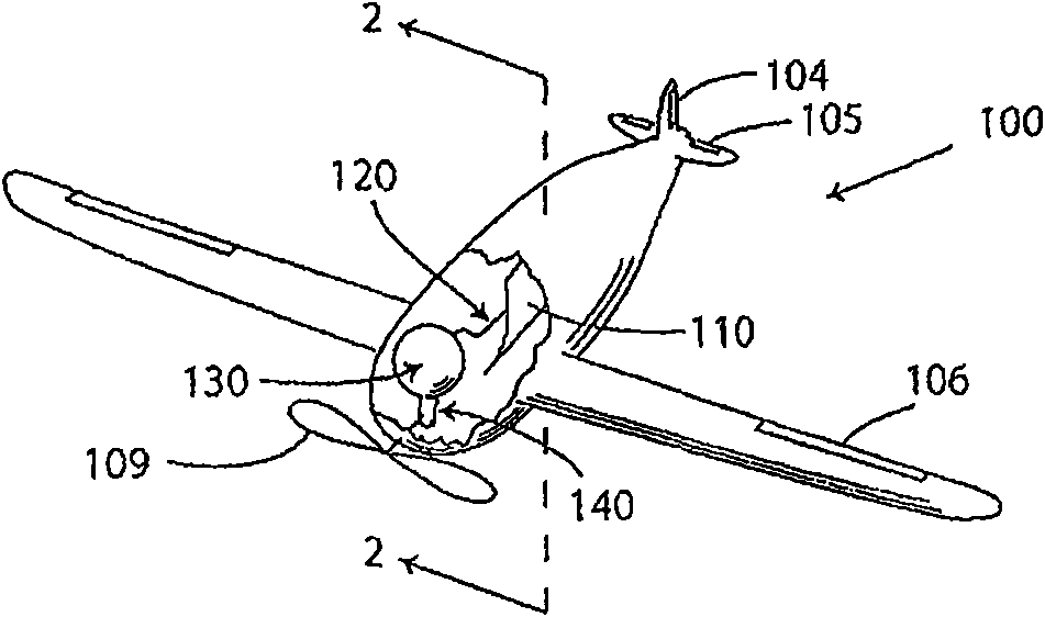
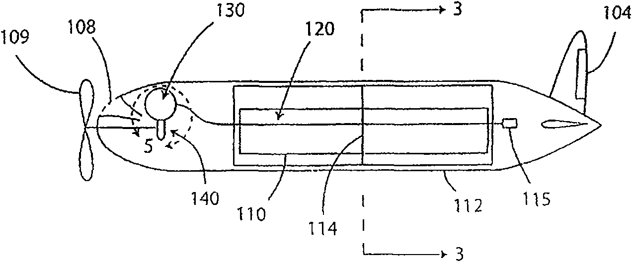
[0055] A solar powered aircraft
[0056] The reference numbers used in the following description for the solar aircraft are listed in Table 2.
[0057] Table 2
[0058] 100
solar aircraft
132
MLI (Multilayer Insulation) layer of highly reflective material
102
wing
133
LiH containment structure
103
134
Hydrogen and other dissociation products of LiH
104
135
Spacer between MLI layers
105
136
106
137
107
transmission
139
108
cooling air inlet channel
140
hot
109
141
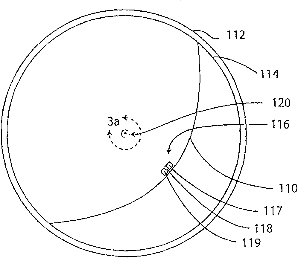
110
Condenser
142
hot side heat exchanger
111
steering elevator
143
regenerator heat exchanger
112
Transparent body shell ...
PUM
 Abstract
Description
Claims
Application Information