
Methods and apparatus for dimming light sources

a technology of light source and dimming device, which is applied in the direction of lighting apparatus, electrical apparatus, light source, etc., can solve the problems of premature opening of the switch, premature unlatching of the switch, and delay of the biasing circui

Inactive Publication Date: 2009-08-13
PURESPECTRUM
View PDF99 Cites 68 Cited by
  • Summary
  • Abstract
  • Description
  • Claims
  • Application Information

AI Technical Summary

Problems solved by technology

Further, the delay of the biasing circuit is typically based on a setting provided by a user.
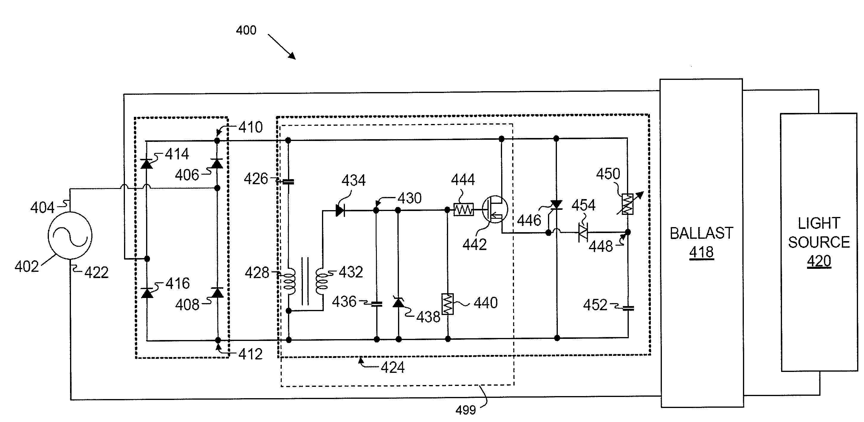
In particular, the charge circuit is operable to provide energy to the switch such that the switch remains biased in the event of an operating condition that, in some instances, would cause the switch to open prematurely.
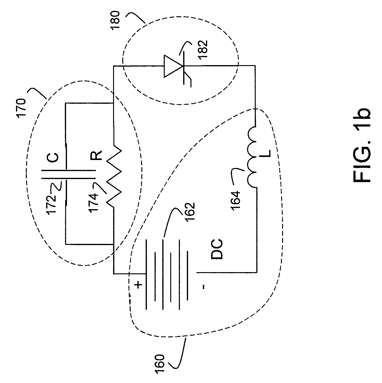
This operating condition is due to a ‘ringing current’ that can cause the switch to become prematurely unlatched, causing undesirable operation.
However, if the voltage generated in the charge circuit exceeds a certain threshold, a further circuit is operable to remove excess voltage from the capacitor.

Method used


Image

  • Methods and apparatus for dimming light sources
  • Methods and apparatus for dimming light sources
  • Methods and apparatus for dimming light sources

Examples


Embodiment Construction

[0016]Methods and apparatus for dimming light sources are described herein. In the described examples, a dimmer circuit allows an operator to control the intensity of the light emitted by a light source with little or no flickering of the light. In addition, the dimmer circuit can be used with ballasts for gas discharge lamps (e.g., fluorescent lamps, etc.) as well as traditional light sources (e.g., an incandescent lamp, etc.) and other types (e.g., LED, etc.). Thus, the dimming system can be used with various light sources.

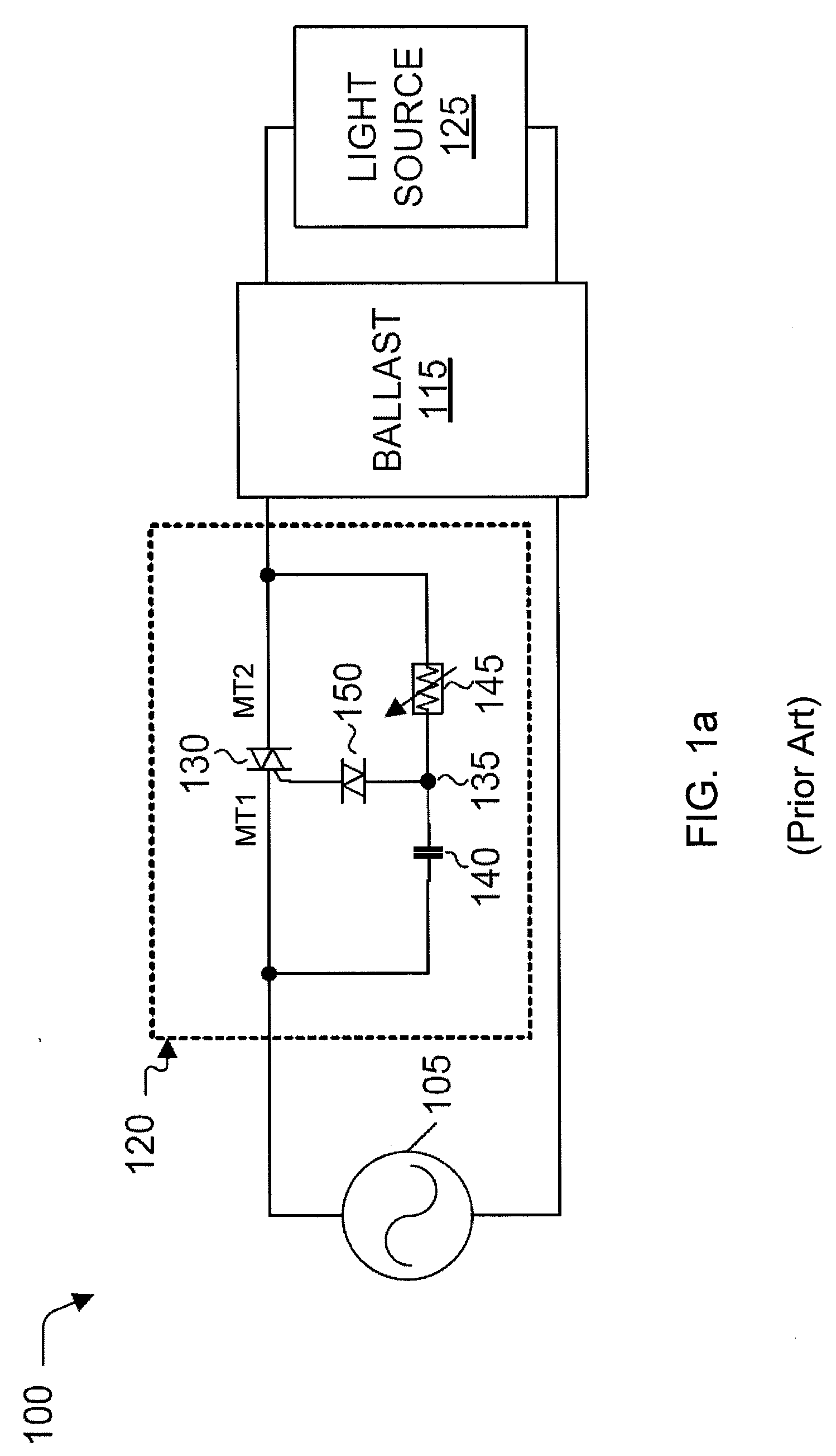
[0017]FIG. 1a illustrates a block diagram of a lighting system 100 implementing a ballast with a conventional dimmer circuit. As will be described in detail below, the conventional lighting system 100 is generally not implemented with conventional gas discharge lamps because of substantial flickering that can occur due to the interaction between a dimmer circuit 120 and a ballast 115. In FIG. 1a, a power source 105 (e.g., an alternating line voltage / current, suc...


PUM


Abstract

Methods and apparatus for dimming light sources are described herein. In certain embodiments, a bias circuit selectively biases a solid state switch during a portion of half-cycle of a line voltage after a settable delay. In some embodiments, the delay of the bias circuit is adjustable by a user, which varies the amount of energy provided to a light source, and the light generated there from. A charge circuit biases the switch for a period of time in the event the bias circuit experiences an operating condition (a ringing current) that may cause the switch to become open during the half-cycle of the line current. As a result of the charge circuit, the light source coupled to the line current does not experience substantial flickering and is compatible with low power compact fluorescent lights. The dimmer can be combined with other components to form a light harvesting system.

Description

CROSS REFERENCE TO RELATED APPLICATIONS[0001]This application is a continuation-in-part of U.S. application Ser. No. 12 / 205,564 filed on Sep. 5, 2008, which in turn claims the benefit under 35 U.S.C. §119(e) to U.S. Provisional Patent Application entitled “Two-Wire Dimmer Switch for Dimmable Fluorescent Lights” filed on Feb. 8, 2008, bearing Ser. No. 61 / 006,967, both of which are herein incorporated by reference for all that each teaches.FIELD OF THE INVENTION[0002]The present invention disclosed herein relates generally to energy saving electronic lighting devices and, more particularly, to methods and apparatus for dimming light sources in an efficient and effective manner.BACKGROUND OF THE INVENTION[0003]In the field of electronic lighting ballasts, some light sources (e.g., gas discharge lamps, fluorescent lamps, etc.) generally present a negative resistance, which causes a power source to increase the amount of current provided to the light source. If not limited, the light sou...

Claims


Application Information

Patent Timeline
Patent Type & Authority Applications(United States)
IPC IPC(8): H05B37/02
CPCH05B41/3924H05B39/044
Inventor KING, RAY JAMES
Owner PURESPECTRUM
Learn More